background image

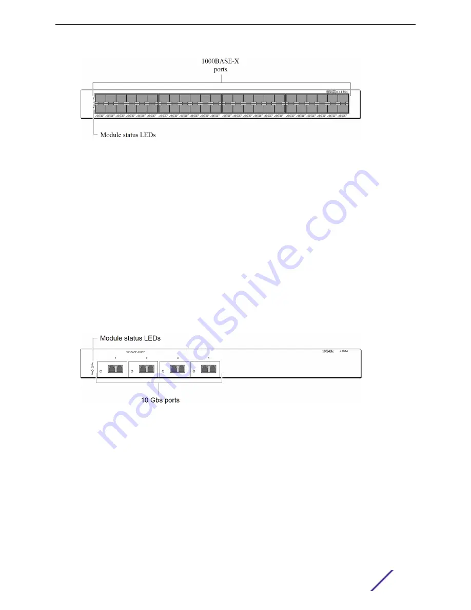
Figure 16: G48Xc I/O Module

In the default configuration of the G48Xc I/O module, all ports:

Are added to the default VLAN as untagged

Inherit the properties of the default VLAN (for example, protocol type and VLANid)

The G48Xc I/O module has the following LEDs:

Module status

Module diagnostics

Port status

For information about the LEDs and their activity on the G48Xc I/O module, see 

I/O Module LEDs

 on

page 35.

10G4Xc I/O Module

The 10G4Xc I/O module (

see the following figure

) has four unpopulated XFP-based 10-gigabit Ethernet

ports.

Figure 17: 10G4Xc I/O Module

In the default configuration of the 10G4Xc I/O module, all ports:

Are added to the default VLAN as untagged

Inherit the properties of the default VLAN (for example, protocol type and VLANid)

The 10G4Xc I/O module has the following LEDs:

Module status

Module diagnostics

Port status

For information about the LEDs and their activity on the 10G4Xc I/O module, see 

I/O Module LEDs

 on

page 35.

BlackDiamond 8000 Series Modules

BlackDiamond 8800 Hardware Install Guide

27

Содержание BlackDiamond 8800 Series

Страница 1: ...BlackDiamond 8800 Hardware Install Guide 121139 00 Published February 2016...

Страница 2: ...notice Trademarks Extreme Networks and the Extreme Networks logo are trademarks or registered trademarks of Extreme Networks Inc in the United States and or other countries All other names including...

Страница 3: ...ironment 47 Rack Specifications and Recommendations 52 Cable Requirements 54 Power Requirements 59 Applicable Industry Standards 62 Chapter 5 Installing the BlackDiamond 8800 Series Chassis 63 Unpacki...

Страница 4: ...ter 11 BlackDiamond Cable Management 121 Cable Holders and Cable Clips 121 Connecting Cable Holders 122 Connecting Cable Clips 123 Chapter 12 Replacing BlackDiamond 8800 Series Chassis Components 125...

Страница 5: ...Modules for BlackDiamond 8800 Series Switches 157 Power Supplies for BlackDiamond 8800 Series Switches 158 Connector Pinouts 160 Index 163 Table of Contents BlackDiamond 8800 Hardware Install Guide 5...

Страница 6: ...see the word enter in this guide you must type something and then press the Return or Enter key Do not press the Return or Enter key when an instruction simply says type Key names Key names are writt...

Страница 7: ...ur documentation so you can find the information you need faster Broken links or usability issues If you would like to provide feedback to theExtreme Networks Information Development team about this d...

Страница 8: ...ions Hardware Documentation BlackDiamond X8 series Switches Hardware Installation Guide Summit Family Switches Hardware Installation Guide for Switches Using ExtremeXOS 21 1 Summit Family Switches Har...

Страница 9: ...e ports The BlackDiamond 8800 series switches include two chassis models BlackDiamond 8806 chassis with slots for installing one or two management modules and up to five I O modules BlackDiamond 8810...

Страница 10: ...ownload a new version of ExtremeXOS and for other functions including capturing debug information and core dump files See the ExtremeXOS User Guide for more information regarding the use of the compac...

Страница 11: ...BlackDiamond 8806 Chassis 1 ESD wrist strap connector 5 Power cord connectors 2 MSM slot 6 Fan tray 3 MSM slot 7 I O module slots 4 Power supplies 8 I O module slots The following figure shows the rea...

Страница 12: ...1 2 3 4 7 8 9 and 10 Two dedicated MSM slots labeled 5 A and 6 B Note On systems running EXOS 15 x slot 6 B can accommodate either an 8800 MSM48c an 8800 e Series I O module or an 8800 c Series I O mo...

Страница 13: ...f the BlackDiamond 8810 Chassis 1 ESD wrist strap connector 5 Fan tray 2 MSM slot 6 I O module slots 3 Power supplies 7 I O module slots 4 Power cord connectors The following figure shows the rear pan...

Страница 14: ...r panel of the BlackDiamond 8810 chassis provides Chassis serial number Ethernet MAC address of the switch Symbols of safety certification Access to the PSU fan controllers Attachment point for option...

Страница 15: ...panel LEDs on the module front panel provide information about the operating status of the module and the ports The BlackDiamond 8800 series switches support the modules listed in the following table...

Страница 16: ...dules 8800 Series Modules 8800 MSM48c 8800 MSM96 8800 c Series I O 8800 e Series I O 8900 MSM128 No No Yes Yes 8900 10G24X c Yes Yes Yes Yes 8900 G96T c Yes Yes Yes Yes 8900 10G8X xl Yes Yes Yes Yes 8...

Страница 17: ...Extreme Networks supported compact flash cards Redundant MSM Activity The BlackDiamond 8800 Series switches can run with a single MSM installed When you install an additional MSM one MSM operates as...

Страница 18: ...aptop to the switch to view and locally manage the switch configurations This port can also be used to connect the system into a parallel management network for administration A button Allows you to s...

Страница 19: ...utton 3 Console port 7 D button 4 Compact flash 8 R button 8800 MSM96 Module Physical Features Figure 7 8800 MSM96 1 Slot for port option card 5 MGMT port 2 Module status LEDs 6 A button 3 Console por...

Страница 20: ...ata ports to the MSM The S G8Xc port option card see the following figure adds eight 1 gigabit SFP data ports to the MSM These data ports operate the same as the ports on the G24Xc I O module Figure 9...

Страница 21: ...ts on the I O modules In the default module configuration all ports Are added to the default VLAN as untagged Inherit the properties of the default VLAN for example protocol type and VLANid For instru...

Страница 22: ...he LEDs on the management Ethernet port are not labeled The left LED indicates link status and the right LED indicates link activity by blinking green Note The data port LEDs on the S G8Xc and S 10G1X...

Страница 23: ...BlackDiamond 8800 Series chassis limitations on feature sets may occur See the ExtremeXOS User Guide and the ExtremeXOS Command Reference Guide for more information about these limitations BlackDiamo...

Страница 24: ...1000BASE T ports that use standard RJ 45 connectors Figure 13 8500 G48T e I O Module You can add an optional S POE daughter card to the 8500 G48T e I O module to provide Power over Ethernet functions...

Страница 25: ...the software on your MSM the module will not be recognized by the software and it will not power up The following error messages are similar to the messages that may be displayed on the console or in...

Страница 26: ...well as the usual Ethernet connection using a single cable The G48Tc I O module supports the IEEE 802 3af PoE specification In the default configuration of the G48Tc I O module all ports Are added to...

Страница 27: ...0G4Xc I O Module The 10G4Xc I O module see the following figure has four unpopulated XFP based 10 gigabit Ethernet ports Figure 17 10G4Xc I O Module In the default configuration of the 10G4Xc I O modu...

Страница 28: ...odules includes G48Te2 see G48Te2 I O Module Caution ExtremeXOS builds earlier than version 12 1 do not support the G48Te2 I O module If you attempt to install one of these I O modules before upgradin...

Страница 29: ...s untagged Inherit the properties of the default VLAN for example protocol type and VLANid Operate in autonegotiation mode The G48Te2 I O module has the following LEDs PoE present Module status Module...

Страница 30: ...pe in slot 2 please program the eeprom Log Error HAL Card Error MSM A Unable to read cardtype for slot 2 Do not install 8900 Series I O modules in any slot of a BlackDiamond 8810 chassis that has a ma...

Страница 31: ...er to a device exceeding the configured limit Enforces class limits by denying power to a device exceeding the class limit Reports and tracks port power faults In the default configuration of the 8900...

Страница 32: ...ix ports Figure 22 8900 G96T c I O Module 1 10 100 1000BASE T ports 3 Port group LED selection button 2 Module and port LEDs In the default configuration of the 8900 G96T c I O module all ports Are ad...

Страница 33: ...the default VLAN for example protocol type and VLANid The 8900 10G8X xl I O module has the following LEDs Module status Module diagnostics Port status For information about the LEDs and their activit...

Страница 34: ...G6X xm I O Module 1 Module and port LEDs 2 QSFP ports When the ports are operating in 40 Gbps mode the ports are numbered from left to right 1 5 9 13 17 and 21 Other port numbers are displayed as not...

Страница 35: ...l type and VLANid The 8900 40G6X xm I O module has the following LEDs Module status Module diagnostics Port status four below each QSFP cage When a port is operating in 40 Gbps mode the farthest left...

Страница 36: ...port option cards installed in the MSM 8c These include the following modules and port option cards G24Xc 8900 G96T c G48Xc 8900 10G24X c G48Tc without S POE card 8900 10G8X xl G48Te2 without S POE ca...

Страница 37: ...left most LED below the port lights and the port operates as a single 40 Gbps link LEDs light blue to indicate 40 Gbps port speed Table 13 Port LEDs for the 8900 40G6X xm Module LED Color and State Me...

Страница 38: ...ow amber blinking Port disabled or Link down Blinking amber green Power fault or insufficient power Port with power disabled Solid green Link up Slow green blinking Port disabled Green blinking Activi...

Страница 39: ...e 15 Power Supply Compatibility in BlackDiamond 8800 Series Switches BlackDiamond Switch Compatible Power Supplies Compatibility Notes BlackDiamond 8806 600W 900W AC power supply AND OR 700W 1200W AC...

Страница 40: ...pply can be used with an Extreme Networks 600 900 W AC power supply in the same chassis Extreme Networks does not recommended using the 700 1200 W AC power supply with an Extreme Networks 1200W DC pow...

Страница 41: ...ger or Sales Manager or purchase a cord from your local supplier All power supply cords must meet the requirements listed in Cable Routing for PoE Devices on page 143 Fuse The Extreme Networks 700 120...

Страница 42: ...urrent conditions Extreme Networks 600 900 W AC Power Supply The following figure shows the Extreme Networks 600 900 W AC UL listed accessory power supply unit Model number 41050 PS 2431 This power su...

Страница 43: ...e an Extreme Networks 600 900 W AC power supply In ExtremeXOS releases 11 3 4 11 4 2 and 11 5 1 the 600 900 W AC power supply is disabled on all chassis In ExtremeXOS releases earlier than those the s...

Страница 44: ...the event of failure immediately return the Extreme Networks 600 900 W AC power supply for a complete replacement Warning Field operators must not attempt to configure or replace fuses in Extreme Netw...

Страница 45: ...long with an input connector on one end and precut wire on the other end that goes to the DC power source see the following figure The connector end has a locking mechanism that locks onto the DC pow...

Страница 46: ...r any reason the power supply does not contain user serviceable parts In the event of failure return the defective 1200 W DC power supply to Extreme Networks for repair or replacement Minimum Software...

Страница 47: ...e that it is ready to migrate to future networking technologies The site planning process has three major parts Meeting site requirements The physical installation site must meet the following require...

Страница 48: ...ark Quincy MA 02169 USA www nfpa org Underwriters Laboratory UL USA only Independent research and testing laboratory UL evaluates the performance and capability of electrical wiring and equipment to d...

Страница 49: ...n electrical contractor for commercial building and wiring specifications Temperature Extreme Networks equipment generates a significant amount of heat It is essential that you provide a temperature c...

Страница 50: ...es not generate any heat Note Up to five adjacent switches will continue to function without safety concerns However product lifetime may degrade with continued exposure to high temperatures in close...

Страница 51: ...the wiring closet Check the appropriateness of floor mats and flooring Connect metal chassis conduit and other metals to ground using dedicated grounding lines Use electrostatically safe equipment an...

Страница 52: ...etworks switches are designed with mounting brackets that provide solid metal to metal connection to the rack If you do not use equipment racks you can attach wiring terminals directly to the mounting...

Страница 53: ...e switch so that you can service it easily Allow a minimum of 48 inches 122 cm in front of the rack and 24 inches 61 cm behind the rack When using a relay two post rack provide a minimum of 24 inches...

Страница 54: ...te the opposite end of any cable Know the types of network devices that your cabling infrastructure can support Consider the following recommendations when setting up a cable labeling system suitable...

Страница 55: ...dow 10 125 m single mode fiber 70 000 1000BASE T 100BASE TX 10BASE T Category 5 and higher UTP cable Category 5 and higher UTP cable Category 3 and higher UTP cable 100 100 100 RJ 45 Connector Jackets...

Страница 56: ...ECT part number 1499520 X also shown MRJ21 to RJ 45 patch panel such as the AMP NETCONNECT part number 1435971 1 Figure 34 Typical Cables for Connection to the 8900 G96T c Module You can order MRJ21 c...

Страница 57: ...he cable to avoid radio frequency RF interference Discharge the RJ 45 Ethernet cable before plugging it into a port on the switch Use plenum rated cable when it is necessary for safety and fire rating...

Страница 58: ...iber optic cable equal 2 inches 5 08 cm minimum for each 90 degree turn as shown in Figure 36 Bend Radius for Fiber Optic Cable on page 59 Note Kinks and sharp bends can destroy or impair the cable s...

Страница 59: ...bit RF interference such as ARC welding equipment Routing UTP cable near electrical motors that contain coils Routing UTP cable near air conditioner units Routing UTP cable near electrical transformer...

Страница 60: ...s Switches on page 158 Warning The chassis does not have a switch for turning power to the unit on and off For systems using an AC power supply power to the chassis is disconnected by removing the wal...

Страница 61: ...arms on certain error conditions Provide short circuit protection Selecting a UPS To determine UPS requirements for your switch answer these questions What are the amperage requirements What is the lo...

Страница 62: ...Standards For more information see the following ANSI TIA EIA standards ANSI TIA EIA 568 A discusses the six subsystems of a structured cabling system ANSI TIA EIA 569 A discusses design consideration...

Страница 63: ...ion to give you more access behind the rack Note Read the information in this chapter thoroughly before you attempt to install the BlackDiamond 8800 Series switch Caution Before you lift a BlackDiamon...

Страница 64: ...Straps Around the Carton 2 Open the flaps and remove the contents from the upper shipping carton see the following figure Figure 38 Removing Contents from the BlackDiamond 8810 Upper Shipping Carton I...

Страница 65: ...39 Removing the Shipping Carton 4 At each corner remove the restraining bolt that holds the BlackDiamond 8810 chassis to the shipping brackets on the shipping pallet see the following figure Figure 40...

Страница 66: ...t of the chassis Figure 41 Gripping Points on the BlackDiamond 8810 Chassis 6 Carefully lift the BlackDiamond 8810 chassis off the shipping pallet and onto the floor see the following figure Note Save...

Страница 67: ...that the BlackDiamond 8810 chassis must be moved to another location or returned to Extreme Networks Unpacking the BlackDiamond 8806 Chassis Caution The BlackDiamond 8806 chassis weighs almost 65 poun...

Страница 68: ...ip lock outward from the carton c Repeat these steps to release each remaining clip lock Figure 44 Clip Locks on the BlackDiamond 8806 Chassis Shipping Carton 3 Slide the shipping carton up over the B...

Страница 69: ...assis 6 Carefully lift the BlackDiamond 8806 chassis off the foam cushion and onto the floor see the following figure Caution Do not use the fan tray handle to lift or maneuver the BlackDiamond 8806 c...

Страница 70: ...he rack mounting screws you will use Use the front mount brackets on the chassis for a front mount rack installation For a mid mount installation obtain one of the following optional kits from Extreme...

Страница 71: ...e left or right side as viewed from the front of the chassis 4 On each side of the chassis use four of the provided screws to attach the appropriate mid mount bracket see the following figure and Figu...

Страница 72: ...800 series chassis 2 Identify the rack location where the chassis will be installed 3 Using four rack mounting screws attach the support bracket to the equipment rack immediately below the chassis loc...

Страница 73: ...vided Be sure that the screws are tight Refer to the following figures for the screw locations Note The following figures show a standard rack mount For mid mount installation use the same mounting lo...

Страница 74: ...assis You need the following materials to ground the chassis Two 10 24 screws One copper standard barrel 2 hole compression grounding lug type LDC equivalent to Panduit part number LCD4 14A L or Thoma...

Страница 75: ...2 Strip 0 5 inch 1 2 cm of insulation from the stranded copper wire cable 3 Insert the stripped wire into the cable lug Caution Be sure that no copper is visible between the lug and the cable insulat...

Страница 76: ...6 Connect the other end of the wire to a known reliable earth ground point at your site Installing the BlackDiamond 8800 Series Chassis BlackDiamond 8800 Hardware Install Guide 76...

Страница 77: ...in restricted access locations dedicated equipment rooms equipment closets or the like in accordance with Articles 110 16 110 17 and 110 18 of the National Electric Code ANSI NFPA 70 All wiring method...

Страница 78: ...plies disabled Caution Even though this process avoids the possibility of over current an I O module may be powered off if a 600 900 W AC power supply is added to a BlackDiamond 8806 switch running in...

Страница 79: ...page 79 shows the maximum DC power output allowed by these power cords when used with each AC power supply Power supply cords are not shipped with the AC power supplies To purchase an AC power cord co...

Страница 80: ...plicable to country of use An AC power cord is not included with Extreme Networks AC power supplies You must obtain a power cord that meets the requirements in Cable Routing for PoE Devices on page 14...

Страница 81: ...AC power supplies repeat steps 1 on page 80 through 3 on page 81 5 After all the power supplies have been installed connect an AC power cord to the AC input connector below each power supply see the...

Страница 82: ...tch 5 To install a replacement power supply follow the steps under Installing the Power Supply on page 80 Installing an Extreme Networks 1200 W DC Power Supply This section describes how to install th...

Страница 83: ...V DC harness provided Power to the 1200 W DC power supply can be from either a 50 A UL approved overcurrent protection breaker or an SELV approved power source in accordance with IEC 60950 1 utilizing...

Страница 84: ...the following figure Note Do not connect the input DC cable to the DC power supply before you install the DC power supply in the chassis Figure 59 Locking Handle on the 1200 W DC Power Supply Install...

Страница 85: ...Use the locking handle to secure the power supply in the power supply bay Figure 60 Installing the 1200 W DC Power Supply in the Power Supply Bay 3 Repeat steps 1 on page 84 and 2 on page 85 to instal...

Страница 86: ...until the locking handle latches 7 At the power source energize the DC circuit for the DC power supply Removing a DC Power Supply Caution The DC power supply may be hot to the touch use thermal prote...

Страница 87: ...input DC cable from the power supply Figure 62 DC Cable Connector on the 1200 W DC Power Supply 4 Pull the handle of the power supply to disconnect the power supply from the power connector at the ba...

Страница 88: ...is chapter thoroughly before you attempt to install or remove a BlackDiamond 8800 Series MSM or I O module Caution Do not attempt to mix modules across Extreme Networks product lines BlackDiamond 8000...

Страница 89: ...SM48c an 8800 e Series I O module or an 8800 c Series I O module On all other EXOS releases this slot can accommodate an MSM only Do not install 8900 Series I O modules in any slot of a BlackDiamond 8...

Страница 90: ...the equipment Transport PC boards only in electrostatic packaging Always place PC boards on a grounded surface before working on them To install a module in a BlackDiamond 8800 Series switch 1 Attach...

Страница 91: ...e caused by sliding the module on the ESD surface Store the module packaging for future use Caution To prevent ESD damage hold the module by the metal rail and front panel only Never touch the compone...

Страница 92: ...ector ejector handle clockwise and completely down When the screw is fully tightened the yellow band around the captive screw is completely hidden Caution Be careful to avoid over torquing and strippi...

Страница 93: ...other appropriate cleaning agent to clean the cable connectors make sure they are free of dust oil and other contaminants 3 If you are using optical fiber cable align the transmit Tx and receive Rx co...

Страница 94: ...o reboot your switch after you use the synchronize command Verifying the Module Installation After you install a module verify that it is working correctly by checking the LEDs on the front panel of t...

Страница 95: ...age 96 This section describes how to remove modules from a BlackDiamond 8800 Series switch BlackDiamond modules are hot swappable You do not need to power the system off to remove a module You need th...

Страница 96: ...r clockwise one quarter turn 90 degrees as shown in Figure 68 Unlocking a Module on page 96 Verify that the red line on each captive screw is in a horizontal position Figure 69 Indications that the Mo...

Страница 97: ...ntive wrist strap permanently connected to the chassis so that it is always available when you need to touch ESD sensitive components Blank Front Panels BlackDiamond switches are shipped with blank fr...

Страница 98: ...e blank front panel Note Tighten the screws of each installed blank front panel before inserting additional modules or blank front panels Otherwise you might unseat modules or blank front panels that...

Страница 99: ...or MSM in the open slot as described in Installing a BlackDiamond 8000 Series Module on page 90 Leave the ESD preventive wrist strap permanently connected to the switch so that the strap is always ava...

Страница 100: ...SM from the chassis to remove an external compact flash memory card You need an ESD preventive wrist strap to remove a compact flash memory card To remove the memory card 1 Use the eject memorycard co...

Страница 101: ...elded serial cables For information about the DB 9 console plug connector see Connector Pinouts on page 160 Logging In for the First Time To log in and manually configure the IP settings 1 Connect a t...

Страница 102: ...default by typing configure vlan default ipaddress 123 45 67 8 255 255 255 0 Your changes take effect immediately 7 Save your configuration changes so that they will be in effect after the next syste...

Страница 103: ...the I O module from the BlackDiamond 8800 Series switch before you install the S POE card You need the following tools and equipment to install an S POE card ESD preventive wrist strap 2 Phillips scr...

Страница 104: ...ts anti static packaging 5 Align the S POE card with the connectors on the I O module as shown in the following figure and following the sequence indicated in the figure carefully press the connectors...

Страница 105: ...ries chassis as described in Removing a BlackDiamond 8000 Series Module on page 95 3 Loosen the spring loaded captive retaining screws on the S POE card until they pop up If the retaining screws are t...

Страница 106: ...8800 MSM48c and 8900 MSM128 are not hot pluggable You must administratively disable the module and remove it from the switch before you install the port option card To install a port option card in an...

Страница 107: ...he captive retaining screws to secure the card in place see the following figure Figure 79 Securing the Port Option Card 8 Re install the MSM following the instructions in Installing a BlackDiamond 80...

Страница 108: ...ch up and hold it out of the way see the preceding figure 5 Using the handle on the card pull straight back from the MSM to disconnect the card from the connectors on the MSM 6 Slide the card out of t...

Страница 109: ...disconnected by removing the wall plug from the electrical outlet Always be sure that all plugs and electrical outlets are easily accessible BlackDiamond 8810 AC Power Cord Retainer Connect all AC pow...

Страница 110: ...AC power cord is firmly plugged into the power outlet see the following figure Figure 83 AC Power Cord Plugged into the BlackDiamond 8810 Switch Power Outlet 4 Align the AC power cord retainer over th...

Страница 111: ...ive screws in the middle and on each end of the power cord retainer 3 Remove the power cord retainer from the front of the switch 4 Disconnect the power cord from the power input connector on the fron...

Страница 112: ...he AC Power Cords Verify that all installed AC power cords are firmly plugged into the power connectors 2 Hold the AC power cord retainer see the following figure Figure 87 BlackDiamond 8806 AC Power...

Страница 113: ...Cords in the Retainer 5 Lay the last two power cords on top of the bottom four cords see the previous figure Removing the BlackDiamond 8806 AC Power Cord Retainer To remove the BlackDiamond 8806 AC po...

Страница 114: ...2 Remove the retainer from the switch BlackDiamond AC Power Cord Retainers BlackDiamond 8800 Hardware Install Guide 114...

Страница 115: ...wing parts Figure 90 PSU Cover Kit on page 115 PSU cover AC power cord management bracket with captive retaining screws Figure 90 PSU Cover Kit You need a 2 Phillips screwdriver to attach the power co...

Страница 116: ...power cord connectors Figure 91 Attaching the AC Cord Retainer 1 Captive retaining screw b Align and tighten the captive retaining screws 4 Set the feet on the base of the cover into the square openin...

Страница 117: ...outward on the top edge of the cover to disengage it from the switch chassis 3 Lift the cover off the AC cord retainer BlackDiamond 8806 PSU Cover The BlackDiamond 8806 PSU cover fits onto the AC powe...

Страница 118: ...U Cover To install the PSU cover 1 If necessary remove the installed AC power cord retainer 2 Make sure that all required AC power cords are connected to the AC power input connectors on the switch 3...

Страница 119: ...d tighten the captive retaining screws 4 Set the feet on the base of the cover into the square openings on the top of the power cord retainer see the following figure Figure 96 Setting the PSU Cover i...

Страница 120: ...SU Cover Removing the BlackDiamond 8806 PSU Cover To remove the PSU cover 1 Press down on the latching tab at each side of the top 2 With the latching tabs pressed down pull outward on the top edge of...

Страница 121: ...than allowing them to hang freely If you must remove a module from the chassis for replacement or repair the cable clips and holders maintain the cable arrangement in front of the chassis for ease of...

Страница 122: ...Each cable holder holds up to 12 separate cables with 6 on each side Connect cable holders end to end as needed to accommodate the number of cables you need to organize To connect the cable holders Bl...

Страница 123: ...the following figure Figure 100 Connected Cable Holders 3 Connect as many cable holders together as you need to manage your cable bundles 4 To disconnect the holders grasp one in each hand firmly and...

Страница 124: ...l the connectors lock into place see the following figure Figure 102 Cable Clip Chain 4 Connect as many cable clips together as you need to manage your cable bundles 5 To disconnect the cable clips p...

Страница 125: ...ssible from the front of the switch Note To avoid long periods of operation without forced air cooling make sure you have the replacement fan tray ready before you start the replacement procedure You...

Страница 126: ...emoving the Fan Tray from the BlackDiamond 8806 Switch on page 126 Figure 103 Removing the Fan Tray from the BlackDiamond 8810 Switch Figure 104 Removing the Fan Tray from the BlackDiamond 8806 Switch...

Страница 127: ...ve it from the chassis Installing the Replacement Fan Tray To install a replacement fan tray into the BlackDiamond 8800 Series switch 1 Support the bottom of the fan tray with one hand as you lift the...

Страница 128: ...lackDiamond 8810 Switch Figure 106 Installing the Fan Tray in the BlackDiamond 8806 Switch 3 Use a 2 Phillips screwdriver to tighten the screws Replacing BlackDiamond 8800 Series Chassis Components Bl...

Страница 129: ...ller unit Refer to the ExtremeXOS User Guide for complete information about upgrading software Before replacing a PSU fan controller make sure that you have access to the back of the switch You need t...

Страница 130: ...e switch see the following figure and Figure 108 Removing the Access Cover from the BlackDiamond 8806 Switch on page 131 Figure 107 Removing the Access Cover from the BlackDiamond 8810 Switch Replacin...

Страница 131: ...e access cover away from the back of the switch The PSU fan controllers are visible in the controller recess 5 Locate the four captive screws on the PSU fan controller you are replacing see the follow...

Страница 132: ...e guide pins in the empty controller recess with the holes on the replacement PSU fan controller 3 Push the replacement PSU fan controller into the empty controller recess until the four captive screw...

Страница 133: ...read the safety information in Safety Information on page 141 Caution Correct lifting procedures for a BlackDiamond 8800 Series chassis require two or more people Before you lift a BlackDiamond 8800...

Страница 134: ...ipment rack 5 Slowly guide the chassis out of the equipment rack using the support bracket for support 6 Carefully lift the chassis off the support bracket and lower it onto wood pallet see the follow...

Страница 135: ...igure Figure 111 Recrating the BlackDiamond 8810 Chassis 8 Set a corner brace at each corner of the chassis and slide the shipping carton down over the chassis see the following figure Figure 112 Plac...

Страница 136: ...s see the following figure Figure 113 Packing Foam for the BlackDiamond 8810 Chassis 10 Close the top flaps on the shipping carton and seal them with packing tape Repacking a BlackDiamond 8800 Series...

Страница 137: ...chassis front panel 2 Remove all modules and power supplies from the BlackDiamond 8806 chassis Follow correct Extreme Networks procedures for removing components 3 Using four rack mounting screws att...

Страница 138: ...hassis place one hand in the empty power supply bay and the other hand in the recessed hand hold on the back panel of the chassis Caution Do not use the fan tray handle to lift or maneuver the BlackDi...

Страница 139: ...n a Using your thumb and index finger squeeze the prongs together b Push the clip lock into place and release the prongs c Repeat these steps to insert each of the remaining clip locks Caution Proper...

Страница 140: ...e 118 BlackDiamond 8806 Chassis Shipping Carton with Nylon Straps Note Nylon straps are optional but are recommended by Extreme Networks for extra security during shipment Installing nylon straps requ...

Страница 141: ...mize the danger to themselves or other persons Considerations Before Installing Consider the following items before installing equipment The system is designed to operate in a typical Telco environmen...

Страница 142: ...educe the risk of electronic damage to the equipment Connect the other end of the strap to the ESD connector on the front of the chassis Leave the ESD preventive wrist strap permanently attached to th...

Страница 143: ...to a PoE capable I O module all connections between the PoE device and the switch must remain inside the same building and use a low voltage power distribution system per IEEE 802 3af Installing Power...

Страница 144: ...the DC power socket on the Extreme Networks DC power supply Do not connect a DC power supply to the DC source power when the power supply is not installed in the chassis doing so would expose a hazar...

Страница 145: ...ltages exceed 240V AC 2P PE such as those used in Norway France and other countries For these applications it is recommended that a transformer be used to step down the voltage to 240V AC from phase p...

Страница 146: ...works switches We recommend that all customers use Extreme Networks optical modules in their Extreme Networks switches Extreme Networks assumes no liability for third party optical modules Although Ex...

Страница 147: ...t werden Sicherer abgeschlossener Arbeitsbereich mit beschr nktem Zugang sodass nur geschultes und qualifiziertes Servicepersonal Zugriff auf das Ger t hat In f r elektrische St rme anf lligen Gebiete...

Страница 148: ...hrleisten Nur Stromkabel verwenden die f r den Einsatz in dem jeweiligen Land zugelassen sind Wechselstromkabel d rfen nicht manipuliert werden Die Wandsteckdose muss in der N he der Anlage installie...

Страница 149: ...en werden Nur f r den Einsatz mit diesem System zugelassene Originalzubeh rteile bzw komponenten verwenden Die Nichtbeachtung dieser Anweisungen kann zu Sch den an der Ausr stung oder sogar zu einem V...

Страница 150: ...Kanada ausgelegt und zugelassen Stromkabel f r den Einsatz au erhalb der Vereinigten Staaten und Kanada werden normalerweise von einem Drittanbieter geliefert und m ssen die folgenden Anforderungen er...

Страница 151: ...de Richtlinien zu beachten 1 Die Batterie nur durch eine identische oder eine gleichwertige vom Hersteller empfohlene Batterie ersetzen 2 Die Batterie gem den Empfehlungen des Herstellers entsorgen Li...

Страница 152: ...b 88 9 kg BlackDiamond 8810 fan tray Weight 6 75 lb 3 06 kg Minimum fan speed 500 RPM Maximum fan speed 6000 RPM BlackDiamond 8810 power supply Weight 7 lb 3 2 kg BlackDiamond 8810 PSU Fan Controller...

Страница 153: ...ods Criteria C 2004 108 EC EMC Directive International CISPR 22 2005 A1 2005 Class A International Emissions CISPR 24 1997_A1 2001 A2 2002 International Immunity VCCI 2010 04 Class A Japan ACMA AS NZS...

Страница 154: ...0 kg 180 m s2 10 g 6 ms 600 shocks modules 50 kg 100 m s2 6 g 11 ms 600 shocks chassis Packaged random vibration 5 to 20 Hz 1 0 ASD w 3 dB oct from 20 to 200 Hz 14 drops minimum on sides corners 39 5...

Страница 155: ...lass A US ICES 003 Issue 4 2004 Class A Canada European EN 55022 2006 A1 2007 Class A EN 55024 1998 A1 2001 A2 2003 EN50121 4 2006 EN IEC 61000 3 2 2006 A2 2009 Harmonics EN IEC 61000 3 3 2009 Flicker...

Страница 156: ...perational sine vibration 5 to 100 to 5 Hz 0 2 g 0 to peak 0 1 oct min Operational random vibration 3 to 500 Hz 1 5g rms ASTM D3580 random vibration unpackaged 1 5g Note Operating temperature refers t...

Страница 157: ...2 93 kg Power 150 W Heat Dissipation 512 BTU 8500 G48T e Weight 7 75 lb 3 52 kg Power 110 W Heat Dissipation 376 BTU 8500 G24X e Weight 6 95 lb 3 15 kg Power 100 W Heat Dissipation 341 BTU 8800 Serie...

Страница 158: ...imensions 1 32 inches H by 6 94 inches W by 11 19 inches D 3 35 cm by 17 63 cm by 28 42 cm Weight 2 20 lb 1 0 kg S 10G1Xc card Dimensions 1 32 inches H by 6 94 inches W by 11 19 inches D 3 35 cm by 17...

Страница 159: ...ndensing Operational shock 30 m s2 3 g Table 37 Specifications for the AC PS Model 41050 600 900 W AC PSU Compatible with the BlackDiamond 8806 switch Typical configuration 3 power supplies Full confi...

Страница 160: ...00 W Operating conditions Operating temperature 0 C to 40 C 32 F to 104 F Operating humidity 10 to 90 relative humidity non condensing Operating altitude 0 m to 3 000 m 0 ft to 9 850 ft Operational sh...

Страница 161: ...hows the pinouts for a 9 pin to 9 pin PC AT null modem serial cable Figure 120 PC AT Serial Null modem Cable Pinouts The following figure shows the port assignments for the MRJ21 connector Technical S...

Страница 162: ...Figure 121 Port to Pin Assignments in the MRJ21 Connector Technical Specifications BlackDiamond 8800 Hardware Install Guide 162...

Страница 163: ...4X c I O module 8900 10G24X c I O module continued features 33 LEDs 35 8900 10G8X xl I O module features 33 LEDs 35 8900 40G6X xm I O module features 34 LEDs 35 8900 G48T xl I O module features 30 LED...

Страница 164: ...Consulting Service International BICSI 54 bundling cable 56 C cables AC power 60 bend radius 56 58 bundling 56 category 5 56 clips 121 123 connecting 93 connecting and disconnecting 94 connecting to...

Страница 165: ...r installing 97 full duplex 10 fuse 600 900 W AC 44 700 1200 W AC 41 G G24Xc I O module features 25 LEDs 35 G48Tc I O module features 26 G48Tc I O module continued LEDs 35 G48Te2 I O module features 2...

Страница 166: ...ets 70 module status LEDs 35 modules see I O modules mounting holes 52 MRJ21 connector 8900 G96T c module 94 cables 94 connecting and disconnecting 94 MSM booting 17 buttons 18 20 console port 18 20 d...

Страница 167: ...d by 59 removing AC power supply 81 removing continued daughter card 105 DC power supply 86 external memory card 100 fan tray 125 front panels 98 MSM port option cards 107 PSU cover 117 120 PSU fan co...

Страница 168: ...r 109 111 installing daughter card 103 installing port option card 106 installing PSU 79 80 installing PSU cover 115 117 repacking 133 replacing fan tray 125 replacing PSU fan controller 129 transitio...

Отзывы: