,QVWDOODWLRQ
#
3URFHGXUH
##
6046
953#
9HFWRU
#
'ULYH
#0#
+$
7968;7
7\SH
#;/<#
DQG
#43#
%UDNH
#
8QLW
#
5DWLQJ
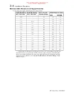
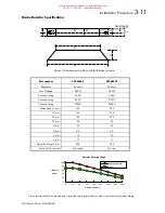
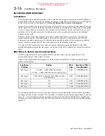
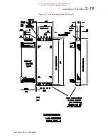
The type 8, 9 and 10 brake units have the following specification -
Maximum braking power: 150%
Operating voltage:
750 - 820 V dc
Maximum duty cycle:
30%
Maximum on time:
20 Seconds
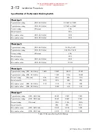
'ULYH
#
VL]H
0D[
1#
%UDNH
#
&XUUHQW
#
:83
9GF
0LQLPXP
#
%UDNH
5HVLVWDQFH
6L]H
#;#2#3<33
553
$
6173#
RKPV
6L]H
#;#2#4433
597
$
51;7#
RKPV
6L]H
#;#2#4653
633
$
5183#
RKPV
6L]H
#<#2#4933
693
$
5133#
RKPV
6L]H
#<#2#4;33
773
$
41:3#
RKPV
6L]H
#<#2#5333
783
$
4193#
RKPV
6L]H
#43#2#5833
858
$
4176#
RKPV
6L]H
#43#2#5;33
9:8
$
4144#
RKPV
%UDNH
#
5HVLVWRU
#
6HOHFWLRQ
#0#
)XUWKHU
#
QRWHV
There are several criteria which must be fulfilled when selecting a braking resistor for safe and proper operation.
These include peak and average power dissipation, resistance and voltage rating. This section describes how to
select the right resistor for the application.
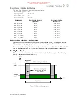
When the motor is decelerating a load, the amount of power it creates is determined by the inertia of the load and the
time the change in speed takes. The rate of change is determined by the MMI parameter
RAMP DOWN TIME
.
&DOFXODWLQJ
#
3RZHU
#
'LVVLSDWLRQ
&DOFXODWLQJ
#
3RZHU
#
'LVVLSDWLRQ
&DOFXODWLQJ
#
3RZHU
#
'LVVLSDWLRQ
&DOFXODWLQJ
#
3RZHU
#
'LVVLSDWLRQ
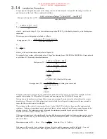
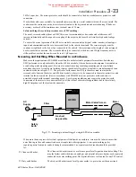
The power dissipation of the resistor needs to be calculated for both peak and average power. The relationship
between these two figures is shown in Figure 3.4.
P o w e r
T i m e
R a m p d o w n
time
Motor running or stopped
Cycle time
P e a k
power
Average
power
Motor decelerating load:
power being fed back
into inverter
)LJXUH
#617#
3HDN
#
DQG
#
$YHUDJH
#
SRZHU
This manual was downloaded on www.sdsdrives.com
+44 (0)117 938 1800 - [email protected]

