6049##
,QVWDOODWLRQ
#
3URFHGXUH
953#
9HFWRU
#
'ULYH
#0#
+$
7968;7
(0&
#
,167$//$7,21
#
*8,'(/,1(6
,QWURGXFWLRQ
This section provides installation guidelines for drive modules and systems to maximise their 'Electro Magnetic
Compatibility' (EMC) in their intended operating environment. All installers must read this section and apply the
advice which is relevant to their application. Pass on this information to others as is appropriate.
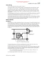
All power drive systems have the potential to produce electrical emissions, both radiated and conducted back into
the AC supply. This is due to the inherent operation of all drives by switching large voltages and currents rapidly
in order to control the motor. Because the drives internal control electronics operates continuously in very close
proximity to the electrically noisy power switching elements, drives are inherently immune to any additional
external electrical noise.
Great care has been taken in the design and selection of suitable EMC filters to provide the correct level of
interface suppression, ease of installation and to ensure that electrical safety is not compromised. The EMC
performance can only be guaranteed to be within the limits specified when the 620 drive modules are installed
together with the recommended EMC filters in accordance with the following instructions.
The subject of EMC is explored in more detail in a separate Eurotherm Application Manual entitled "EMC
Installation Guidelines for modules and systems’, part number HA388879, available from your local Eurotherm
office.
(0&
#
)LOWHUV
#
WR
#
5HGXFH
#
/LQH
#
&RQGXFWHG
#
1RLVH
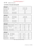
An EMC supply filter may be used with each 620 drive module to reduce the line conducted noise. The
recommended filters are listed in table 3.3 below.
7DEOH
#616#
$&
#
6XSSO\
#
)LOWHU
#
3DUW
#
1XPEHUV
#
IRU
#
&RQIRUPDQFH
#
ZLWK
#
(1
88344#
&ODVV
#
%
#+
VXLWDEOH
#
IRU
#
ERWK
JHQHULF
#
HQYLURQPHQWV
,
(XURWKHUP
3URGXFW
5DWLQJ
:DWW
/RVV
(XURWKHUP
#
)LOWHU
3DUW
#
1XPEHU
953#
7\SH
#7
31:8
N:
#0#818
N:
#+6;3
9
#
WR
#793
9
,#)
31:8
N:
#0#515
N:
#+53;
9
#
WR
#573
9
,#
FRQVWDQW
#
WRUTXH
53
:
&2
6;;<99
8
354
953#
7\SH
#7
:18
N:
#+6;3
9
#
WR
#793
9
,#)#7
N:
#+53;
9
#
WR
#573
9
,
FRQVWDQW
#
WRUTXH
68
:
&2
6;;<99
8
368
953#
7\SH
#8
$OO
58
:
&2
6;;<99
8
378
953#
7\SH
#9
$OO
:8
:
&2
797386
8
3<8
953#
7\SH
#:
$OO
48;
:
&2
797386
8
533
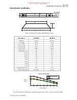
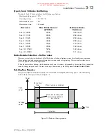
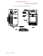
The recommended EMC filters for the type 4 and 5 620 are to be mounted behind the drive module (underfloor
mounting) and share the same footprint. They are suitable as standard for cubicle mount applications, as shown in
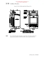
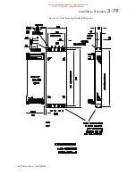
figure 3-7. For wall mounting a purpose designed pressed steel conduit (Part No. BA388844) is supplied with
the gland box, for mounting between the filter body and gland box is shown in the mechanical mounting drawing
figures 3-8.
This manual was downloaded on www.sdsdrives.com
+44 (0)117 938 1800 - [email protected]

