805;#
)XQFWLRQ
#
%ORFNV
953#
9HFWRU
#
'ULYH
#0#
+$
7968;7
63(('
63(('
63(('
63(('
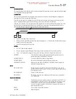
Note: This is only applicable to the 620Comm and 620L.
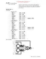
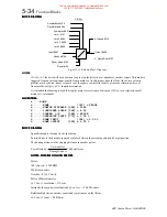
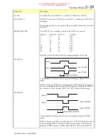
Calculates reference speed from the reference encoder. Speed is normalised to 100% which equates to the
maximum speed rpm parameter taking into account the number of lines on the reference encoder.
REFSPEED
Speed diagnostic calculated from Reference encoder.
MAX SPEED RPM
100% for reference encoder.
ENCODER LINES
Number of lines on the reference encoder used for the calculation of
reference speed.
SCALED REF SPEED
If TRUE reference speed is scaled by REF SCALE A / REF SCALE B.
3,'
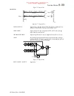
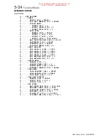
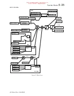
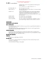
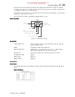
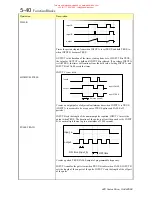
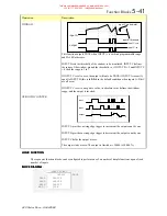
The PID Block allows the drive to be used in applications where a trim is required from an external loop. The
PID input can be load cell tension, dancer position or any other transducer feedback such as pressure, flow etc.
The most commonly encountered applications in web transfer and winding are:
Section Control with PID trim on speed demand. The PID input is either load cell tension or dancer position
feedback.
)($785(6
)($785(6
)($785(6
)($785(6
1.
Independent adjustment of gain and time constants.
2.
Additional first-order filter (F).
3.
Functions P, PI, PD, PID with/without F individually selected.
4.
Ratio and divider for scaling each input.
5.
Independent positive and negative limits.
6.
Output scalar (Trim).
%/2&.
#
',$*5$0
%/2&.
#
',$*5$0
%/2&.
#
',$*5$0
%/2&.
#
',$*5$0
(1$%/(
,17(*5$/
#
'()($7
,1387
#4
5
'
5$7,2
4
',9,'(5
4
5
'
5$7,2
5
',9,'(5
5
+
-
,1387
#5
326
#
/,0,7
1(*
#
/,0,7
2
2
3
#
6&$/(5
3,'
#
287387
.S
+4.
V7L
,+4.
V7
V7L
+4.
V7I
,
3523
#
*$,1
,17(*5$/
#
7&
'(5,9$7,9(
#
7&
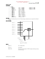
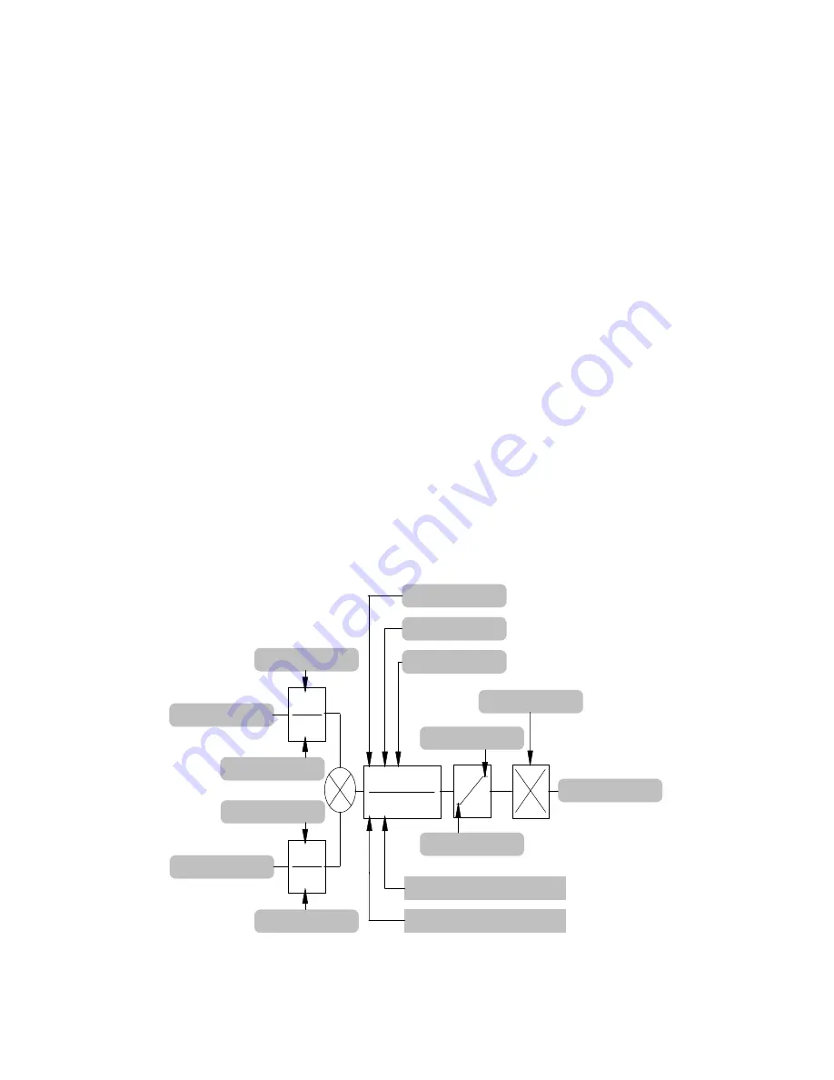
Figure 5.19 PID
This manual was downloaded on www.sdsdrives.com
+44 (0)117 938 1800 - [email protected]


