3UH
0
,QVWDOODWLRQ
#
3ODQQLQJ
##
504
953#
9HFWRU
#
'ULYH
#0#
+$
7968;7
&KDSWHU
#5##
3UH
0
,QVWDOODWLRQ
#
3ODQQLQJ
,1752'8&7,21
This chapter contains a functional description of the 620 Vector Drive to enable a sound understanding of the
system, and notes for consideration prior to installation.
)81&7,21$/
#
29(59,(:
The 620 Vector enables very high performance control of 3-phase AC induction motors fitted with a compatible
encoder. It offers the user great system flexibility, allowing easy integration into various control schemes. The plain
language Man-Machine Interface (MMI) greatly simplifies setting up and commissioning the 620 Vector.
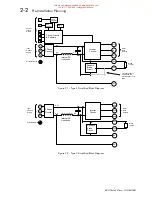
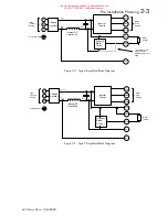
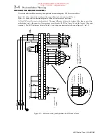
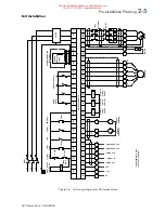
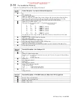
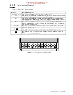
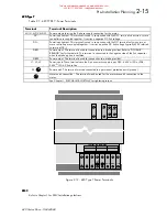
A simplified block diagram of a 620 is shown in Figure 2.13. This illustrates the basic internal arrangement of the
drive with the circuitry split between the control circuits and power circuits.
The control circuits are common to all types of the 620 Vector Drive.
Chassis types 5 and 7 use a slightly different power circuit from types 4 and 6. The general principles of operation
remain the same, however.
&RQWURO
#
&LUFXLWV
#
DQG
#
6RIWZDUH
The control circuits and software element contain the intelligence of the 620 Vector series. They comprise a
sophisticated microprocessor system with digital and analogue inputs and outputs, the MMI and circuits to interface
between the microprocessor and the inverter circuits.
Speed feedback signals from the motor shaft encoder are processed by the microprocessor to determine the rotational
speed of the shaft. An PI algorithm within the software uses this information to produce varying gate drive signals to
the inverter circuits. These signals cause the inverter to output the required voltage and frequency for a particular
motor speed.
Analogue inputs to the microprocessor are digitised and can be used to set parameters such as speed.
Digital inputs to the microprocessor signal various commands and conditions such as stop, start and required
direction of rotation.
Digital outputs from the microprocessor (e.g. Health) can be used by external control equipment.
A detailed block diagram of the logical blocks which comprise the control circuits and software is shown in Figure
2.13.
3RZHU
#
&LUFXLWV
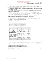
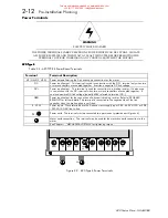
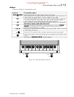
The 3-phase supply input on terminals L1, L2 and L3 is rectified to give a DC output to the DC Link capacitors,
which smooth the DC power. The DC power is fed to the inverter circuits, which convert the fixed voltage DC into
three phase variable frequency and voltage drive outputs to the motor. The frequency and voltage are set by the gate
drive signals from the microprocessor.
During motor deceleration or at other times when the motor acts as a generator, energy flows from the motor into the
DC link capacitors and causes the DC link voltage to rise. The drive will trip if the DC link voltage rises above a
pre-set level, to avoid damage to the drive.
'\QDPLF
#
%UDNLQJ
If the dynamic braking option is fitted, an external brake resistor is switched across the DC Link by the Dynamic
Brake Switch to dissipate the excess energy and prevent the drive from tripping.
Chapter 3 describes the power and resistance rating requirements for the dynamic braking resistor.
%XLOW
0
LQ
#
GLDJQRVWLFV
Number and logic diagnostics are values and settings that can be displayed via the diagnostic menu within the MMI.
These values are read-only and are provided for the user to determine operating or fault conditions. Refer to
Chapter 6 for further information and descriptions of the diagnostics.
This manual was downloaded on www.sdsdrives.com
+44 (0)117 938 1800 - [email protected]


