'LDJQRVWLFV
#
DQG
#
)DXOW
#
)LQGLQJ
##
906
953#
9HFWRU
#
'ULYH
#0#
+$
7968;7
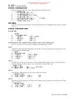
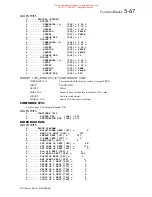
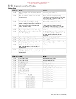
ANIN 1 (C3)
Diagnostic displaying the current state of the analogue input 1 (C3), by default
this is connected to Speed setpoint no. 1.*
ANIN 2 (C4)
Diagnostic displaying the current state of the analogue input 2 (C4), by default
this is connected to Direct speed setpoint no. 2 / current demand.
ANIN 3 (F2)
Diagnostic displaying the current state of the analogue input 3 (F2), by default
this is connected to Speed setpoint no. 3 (ramped).*
ANIN 4 (F3)
Diagnostic displaying the current state of the analogue input 4 (F3), by default
this is unconnected.
ANIN 5 (F4)
Diagnostic displaying the current state of the analogue input 5 (F4), by default
this is unconnected.
ANOUT 1 (C5)
Diagnostic displaying the current state of the analogue output 1 (C5), by
default this is connected to
S
peed feedback.*
ANOUT 2 (F5)
Diagnostic displaying the current state of the analogue output 2 (F5), by
default this is connected to Torque demand. *
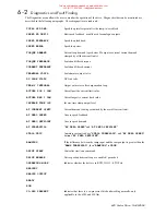
COAST STOP
PROGRAM STOP
State of program stop (terminal B8).
When B8 is at 24V then "
PROGRAM STOP
" is
FALSE
START (B7)
Diagnostic displaying the current state of the start input 2 (B7), by default this
is connected to Start terminal.
JOG INPUT (B6)
Diagnostic displaying the current state of the Jog input 2 (B6), by default this
is connected to Jog Input terminal.
ENABLE (B8)
Diagnostic displaying the current state of the Enable input (B8), by default this
is connected an Electronic Enable (ON = Enabled).
DIGIN 1 (E2)
Diagnostic displaying the current state of the digital input 1 (E2), by default
this is connected to Ramp hold input (ON = Hold).*
DIGIN 2 (E3)
Diagnostic displaying the current state of the digital input 2 (E3), by default
this is connected to Preset Select input 1. *
DIGIN 3 (E4)
Diagnostic displaying the current state of the digital input 3 (E4), by default
this is connected to Preset Select input 2. *
DIGIN 4 (E5)
Diagnostic displaying the current state of the digital input 4 (E5), by default
this is connected to Preset Select input 3. *
DIGOUT 1 (E6)
Diagnostic displaying the current state of the digital output 1 (E6), by default
this is connected to At zero speed.
DIGOUT 2 (E7)
Diagnostic displaying the current state of the digital output 2 (E7), by default
this is connected to Drive HEALTH. and is always ON when the start is low.
This differs from Health as displayed on a front panel l.e.d. which remains of
until health is reset by the drive being restarted.
DIGOUT 3 (E8)
Diagnostic displaying the current state of the digital output 3 (E8), by default
this is connected to drive READY
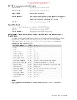
RAISE/LOWER O/P
Value of the raise / lower ramp function.
PRESET O/P
O
utput of Preset function block.
SPT SUM O/P 1
O
utput of Setpoint Sum 1 function block.
This manual was downloaded on www.sdsdrives.com
+44 (0)117 938 1800 - [email protected]

