3UH
0
,QVWDOODWLRQ
#
3ODQQLQJ
##
5044
953#
9HFWRU
#
'ULYH
#0#
+$
7968;7
',3
#
6ZLWFKHV
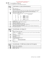
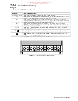
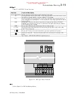
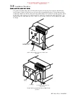
The control PCB also houses a set of dual in-line package (DIP) switches, located to the left of the terminals. The
twelve switches are numbered, starting with 1 on the left.
The switches are ON when in the UP position (towards the centre of the drive) and OFF when in the DOWN position
(towards the edge of the drive).
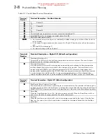
Switch 1 selects 2 or 4 wire serial communications, 2-wire is selected when the switch is ON, and 4-wire when the
switch is OFF (only 4 wire supported).
Switch 2 connects or disconnects the line termination network between terminals G3 and G4. The network is
connected when the switch is ON, and disconnected when the switch is OFF. The drive furthest from the host should
have switch 2 ON, all other drive should switch 2 in the OFF position.
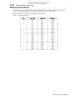
Switches 3 and 4 are only significant on 620 Link versions of the drive, which are equipped with fibre-optic
communications facilities. The switches control the transmitter output power as follows:
Switch 5 is used to test the transmit output power by turning the transmitter permanently ON, when the switch is
ON. In this mode a light meter can be used to check that the received power at the far end of the optical fibre is
within limits. The switch must be OFF in the normal operation.
7DEOH
#516#
7UDQVPLWWHU
#
3RZHU
#
',3
#
6ZLWFKHV
527#
ZLUH
6ZLWFK
#4
70
:LUH
#
56
07;8
2II
50
:LUH
#
56
07;8#+
1RW
#
6XSSRUWHG
,
2Q
7;
#
3RZHU
6ZLWFK
#6
6ZLWFK
#7
6ZLWFK
#8
/RZ
2II
GRQ
*
W
#
FDUH
2II
0HGLXP
2Q
2II
2II
+LJK
2Q
2Q
2II
7HVW
#
0RGH
GRQ
*
W
#
FDUH
GRQ
*
W
#
FDUH
2Q
)HHGEDFN
#
(QFRGHU
6ZLWFK
#:
6ZLWFK
#;
6ZLWFK
#<
<
Y
±
4#
,QSXW
#
7KUHVKROG
2II
2II
2II
7
Y
±
4#
,QSXW
#
7KUHVKROG
2Q
2Q
2Q
5HIHUHQFH
#
(QFRGHU
6ZLWFK
#43
6ZLWFK
#44
6ZLWFK
#45
<
Y
±
4#
,QSXW
#
7KUHVKROG
2II
2II
2II
7
Y
±
4#
,QSXW
#
7KUHVKROG
2Q
2Q
2Q
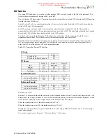
Switch 6 is not used.
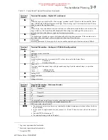
Switches 7 to 9 control the threshold sensitivity for the feedback encoder: switch 7 controls the A input, switch 8 the
B input and 9 the Z input. Switches 10 to 12 control threshold sensitivity for the reference encoder (optional): switch
10 controls the sensitivity for the A input, switch 11 the B input and 12 the Z input.
When the switches are set ON, threshold sensitivity is 4V
±
1V.
When the switches are set to OFF, threshold sensitivity is 9V
±
1V.
Usually the switches will be set to give a threshold of 4V when using a differential encoder, and to 9V when using a
single ended encoder.
For encoder supply refer to Chapter 5: “Function Blocks” - Calibration.
This manual was downloaded on www.sdsdrives.com
+44 (0)117 938 1800 - [email protected]


