507##
3UH
0
,QVWDOODWLRQ
#
3ODQQLQJ
953#
9HFWRU
#
'ULYH
#0#
+$
7968;7
,167$//$7,21
#
:,5,1*
#
',$*5$06
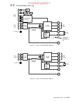
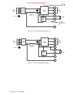
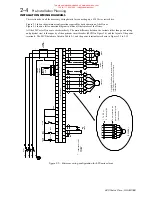
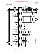
This section shows all the necessary wiring details for connecting up a 620 Vector series drive.
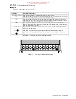
Figure 2.5 shows the minimum configuration required for basic operation of the Drives.
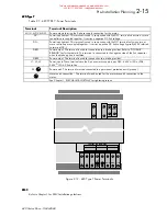
Figure 2.6 shows a full connection diagram to utilise all the features of the Drives.
All the 620 Vector Drives are wired similarly. The main difference between the variants (other than power rating
and physical size) is the capacity of the upstream circuit breaker (MCB1 in Figure 2.6) and the layout of the power
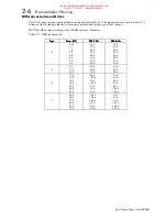
terminals. The MCB details are listed in Table 2-1, and the power terminals are shown in Figures 2.9 to 2.12.
L3
L1
MCB1
MOTOR
M
L1
L2
FILTER
(OPTIONAL)
M2/V
M1/U
M3/W
LABELLED DB1 & DB2
ON TYPE 7
CHASSIS
*
RAM
P
SPEED
L3
PE
L2
F.STOP
GND
C2
C1
B4
B5
E.STOP
C6
C3
B7
STOP
COAST
STOP
FAST
START
A
A
ENCODER
MOTOR
THERMISTOR
B
15V
0V
B
E
620 VECTOR DRIVE
B8
B9
24V24V
A1
A2
ASSY
.
A4
A3
*
A7
A8
DBR
*
B1
A9
EE
B2
DC+
D
C
-
E
DC+
D
C
-
E
DYNAMIC
BRAKING
RESISTOR
BRAKE
+
A1
A2
A4
A3
A7
A8
1. To PE or
2. terminal A9
Encoder
To be installed as
per manufacturers
instructions.
+HQJVWOHU
#
(QFRGHUV
#
DUH
#
UHFRPPHQGHG
UHIHU
#
WR
#
(XURWKHUP
#
'ULYHV
#
IRU
#
PRUH
LQIRUPDWLRQ
1
)LJXUH
#518#0#
0LQLPXP
#
ZLULQJ
#
FRQILJXUDWLRQ
#
IRU
#953#
VHULHV
#
GULYHV
This manual was downloaded on www.sdsdrives.com
+44 (0)117 938 1800 - [email protected]


