6HWWLQJ
0
XS
#
DQG
#
&RPPLVVLRQLQJ
##
70<
953#
9HFWRU
#
'ULYH
#0#
+$
7968;7
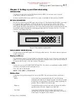
9. Press to select
MAG CURRENT %
and then press
M
. Read the “no load current” from the motor nameplate,
and use the
and
buttons to set the
MAG CURRENT %
parameter to the specified figure ((No Load
Current / Motor Rating RMS) * 100%). Press
E
.
If the “no load current” is not available, set the
MAG CURRENT %
to 30-40% for motors less than 30kw and
20-30% for motors > 30kw.
10. Press
to select
ROTOR TIME CONST
and then press
M
. This parameter sets up an initial estimate of the
rotor time constant which Autotune will later optimise. For motors up to 2.2kW use 100.0ms, between 2.2kW
and 7.5kW use 200.0ms, between 7.5kw and 22kW use 400.0ms and for larger motors use 800.0ms. Use the
and
buttons to set the
ROTOR TIME CONST
parameter to the required figure. Press
E
.
11. At this point almost all of the required basic parameters have been entered and further parameters can only be
determined by running the drive. All the parameters should now be saved. To save the parameters, press
E
M
which will select
SAVE PARAMETERS
option, and then press
M
. Press
to save the parameters.
The display will say
FINISHED
after a second or so when the process is complete. Press
E
M
to return
to the Configure Drive menu.
When power is removed from the product it must not be re-applied for a period of 30 seconds to
allow the inrush limit circuit to operate correctly.
6HWXS
#
6WHS
#8####
5XQ
#
WKH
#
GULYH
The next step is to run the drive.
•
UNPREDICTABLE MOTION, ESPECIALLY IF MOTOR PARAMETERS ARE INCORRECT.
•
ENSURE NO PERSONNEL ARE IN THE VICINITY OF THE MOTOR OR ANY CONNECTED MACHINERY.
•
ENSURE THAT THE EMERGENCY STOP CIRCUITS FUNCTION CORRECTLY BEFORE RUNNING THE
MOTOR FOR THE FIRST TIME.
•
WHEN THE DRIVE IS RUN FOR THE FIRST TIME ROTATION WILL BE OF UNKNOWN DIRECTION,
MAY BE JERKY AND SPEED CONTROL MAY NOT OPERATE CORRECTLY.
•
ENSURE THAT NO MACHINERY CONNECTED TO THE MOTOR WILL BE DAMAGED BY
UNPREDICTABLE MOTION.
1. Press
LOCAL
to put the drive into LOCAL MODE. The LOCAL LED should light.
2. Use
the and
buttons to set a speed demand of between 5% and 10% of full speed (the actual value is not
critical).
3. Press
I
to start the motor. The RUN LED should illuminate. (If any error messages occur on the MMI, refer
to Chapter 6, "Diagnostics").
4. Listen to and look at the motion of the motor. If the encoder sign is correct the motor will rotate smoothly and
respond to changes in speed demand or direction. To check this, use the
and
buttons to increase the
speed to about double the first figure, and then use the
button to change the direction of rotation. If it
accelerates and changes direction smoothly, this confirms that the encoder sign is set correctly.
5. If the ENCODER SIGN is incorrect, the motor will rotate in a jerky and/or noisy manner. Alternatively, it may
rotate smoothly at a very low speed but not respond to changes in speed demand or direction. In either case the
encoder sign must be changed. Paragraph 7 describes how to change the encoder sign.
6. If the motor rotates in the wrong direction, press
0
to stop the motor then power down the entire drive
assembly, wait 3 minutes for the DC Link capacitors to discharge then swap motor drive cables M1 and M2.
Re-start the Initial Setup procedure from step 1. The encoder sign will have been changed by the change in
motor direction as described in step 4.
This manual was downloaded on www.sdsdrives.com
+44 (0)117 938 1800 - [email protected]

