Overview
CAN-CBX-AI420
Manual • Doc.-No.: C.3030.21 / Rev. 1.4
Page 9 of 103
! "#
$ %
&
'()
% "
* +
#,#
-%&
. /
&%-/+
0#$+/$/1
- +/&&*
+
0234536
7
89 :;98
< 8
;
;=
>
?
;9@ <
/A*+
BCD
D&"
E
5
FG
'H
I
7 I
J
<
9 :
K
?
:
9
:
I>
L
M
NO PQR
S
T UV
I
SW
9 :
I
T OPQP S
X YO ZT
'
[
'
'
/1\*+-*
+
#,#-%&
. /&
%-/+
.6]
^_`
#,#-%&
. /&
%-/+
.6]
^_`
5
(1%
&/,
. 1D
C-
QM
9 :
I
T OPQT N S
YO ZT
a
7
8 9: ;
9 8
< 8;
E
_'!%
11*
&
E
5 _
b#-
c d_('
(6
6`E
2ef
E_'!
%11*
&
E
5 _
b#-
c d_('
(
66`E
2ef
'['_
'
/ 1
\*+-* +
1. Overview
1.1 Description of the Module
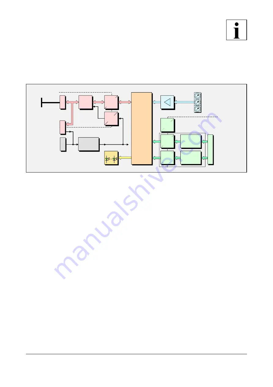
Fig. 1: Block circuit diagram of the CAN-CBX-AI420 module
The CAN-CBX-AI420 module is equipped with a MB90F497 microcontroller, which buffers the CAN
data into a local SRAM. The firmware is stored in the flash. Parameters are stored in a serial EEPROM.
The four differential analog inputs are converted by two sigma-delta-converters. The
gh
-converters
offer a resolution of up to 24 bit. The resolution achieved during the operation depends essentially on
the sample time chosen and on the external circuit.
The input voltage range of the analog inputs is ±10 V.
The inputs are connected via a 12-pin screw-/plug connector. The analog inputs are electrically isolated
by digital isolators for the protection of the other components.
The power supply voltage and the CAN-bus connection can either be fed via the InRailBus connector,
integrated in the top-hat rail or via separate plugs.
The ISO 11898-compliant CAN interface allows a maximum data transfer rate of 1 Mbit/s. The CAN
interface is electrically isolated by a dual digital isolator and a DC/DC-converter.
The CANopen node number and the CAN bit rate can be configured via three coding switches.


