


4. Troubleshooting (DeviceNet)
270
RC700 / RC90 Option Fieldbus I/O Rev.14
♦
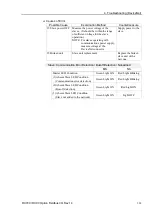
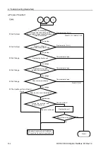
Causes of Error
Possible Cause
Examination Method
Countermeasure
Voltage drop of
communications
power supply
Measure voltage of
communications power supply at
the master unit.
→
Normal: 11V or more between
V+ and V-
If the voltage is 11 to 14 V, the
master unit is a possible cause.
Fix the problem on it.
Check voltage of the power
supply.
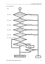
Disconnected
terminating
resistors
Cable
disconnection
Disconnected
connector
Disconnected
signal wire
(1)
Check that terminating
resistors are connected to
both ends of the network.
(2)
Measure resistance between
signal wires with
communications power
supply OFF.
→
Normal: 50 to 70
Ω
Measuring point: Connection
of the master
For details, refer to the section
4.1.3.1 Connection Problem
.
Fix the problem.
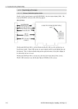
How to find the trouble
point:
Remove the terminating
resistor on one end of the
network. The trouble point
is where resistance
changes from 120
Ω
.
Loose connector
Loose signal wire
Check for the connection of
connectors and signal wires.
→
The connectors and signal
wires should be firmly
connected.
Checkpoint: Between the
master and its slaves
For details, refer to the section
4.1.3.2 Loose Connector and
Signal Wire
.
Connect the connectors
and signal wires again.
All slaves power
OFF
Measure the power voltage of the
slaves. (It should be within the
range of sufficient voltage for
slave operation.)
Supply power to the slaves.
Master unit
configuration
(1)
Start applicomIO Console
application and check that the
configuration has no
difference with the network
condition.
(2)
Check that the configuration
data were written in flash.
For details, refer to the section
4.1.3.6 EPSON RC+ Master
Configuration
.
Change the configuration.
Содержание RC700
Страница 1: ...Robot Controller RC700 RC90 Option Fieldbus I O Rev 14 EM198C4088F ...
Страница 2: ...Robot Controller RC700 RC90 Option Fieldbus I O Rev 14 ...
Страница 8: ...vi RC700 RC90 Option Fieldbus I O Rev 14 ...
Страница 12: ...Table of Contents x RC700 RC90 Option Fieldbus I O Rev 14 ...
Страница 74: ...2 Installation 62 RC700 RC90 Option Fieldbus I O Rev 14 17 DeviceNet Slave is connected and the icon appears ...
Страница 165: ...2 Installation RC700 RC90 Option Fieldbus I O Rev 14 153 PCI CIFX 50 RE PCI Express CIFX 50E RE ...
Страница 183: ...2 Installation RC700 RC90 Option Fieldbus I O Rev 14 171 17 EtherNet IP Slave is connected and the icon appears ...
Страница 340: ...5 Maintenance Parts List 328 RC700 RC90 Option Fieldbus I O Rev 14 ...


