


4. Troubleshooting (DeviceNet)
258
RC700 / RC90 Option Fieldbus I/O Rev.14
4.1.1 Examining a Problem
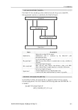
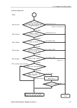
4.1.1.1 Scanner Board Diagnostic LEDs
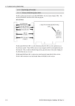
The DeviceNet master board used with EPSON RC+ has two status display LEDs. The
layout of the LEDs is shown in the following figure.
PCU-DVNIO
4-pin Terminal
Watchdog Port
(Do not use this port.)
DeviceNet Port
LED (2)
(Unused)
RJ45 Connector
(Unused)
Jumper Pin for Board Address Setting
C0 C1 C2
JP1
JP1
0
1
Status Display LED (2)
The Module/NetWork LED is on the left side and the IO LED is on the right side seen
from the rear panel. These LED names are used in applicomIO Console application and
this manual. Only in this troubleshooting section, general names of the status display of
the DeviceNet device are used.
The Module/NetWork LED is referred to as the Network Status (NS) in this section.
The IO LED is referred to as the Module Status LED (MS) in this section.
Содержание RC700
Страница 1: ...Robot Controller RC700 RC90 Option Fieldbus I O Rev 14 EM198C4088F ...
Страница 2: ...Robot Controller RC700 RC90 Option Fieldbus I O Rev 14 ...
Страница 8: ...vi RC700 RC90 Option Fieldbus I O Rev 14 ...
Страница 12: ...Table of Contents x RC700 RC90 Option Fieldbus I O Rev 14 ...
Страница 74: ...2 Installation 62 RC700 RC90 Option Fieldbus I O Rev 14 17 DeviceNet Slave is connected and the icon appears ...
Страница 165: ...2 Installation RC700 RC90 Option Fieldbus I O Rev 14 153 PCI CIFX 50 RE PCI Express CIFX 50E RE ...
Страница 183: ...2 Installation RC700 RC90 Option Fieldbus I O Rev 14 171 17 EtherNet IP Slave is connected and the icon appears ...
Страница 340: ...5 Maintenance Parts List 328 RC700 RC90 Option Fieldbus I O Rev 14 ...


