Epson Stylus Photo R280/R285/R290/Epson Artisan 50/Epson Stylus Photo T50/T59/T60/P50
Revision C
Chapter 4 Disassembly/Assembly
4.3.3 P/S Assy (Removing Control Boards)
71
Confidential
4.3.3 P/S Assy
Parts/Components need to be removed in advance
Printer Cover / Paper Support Assy / Upper Housing / Main Board Unit / Panel Assy /
Cover Open Sensor / Printer Mechanism
Removal procedure
1.
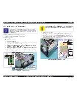
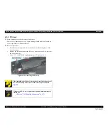
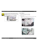
Peel off the acetate tape and remove the ferrite core from the groove of the
Lower Housing.
2.
Remove the screw that secures the P/S Assy, and remove the P/S Assy from
the Lower Housing.
•
Screw
: C.B.P M3x10 (tightening torque: 5-7 kgf.cm)
(No.4)
Figure 4-34. Removing the P/S Assy
When installing the P/S Assy, put the ferrite core into the groove of
the Lower Housing and secure it with acetate tape as shown in
Fig.4-34
.
A D J U S T M E N T
R E Q U I R E D
Whenever the P/S Assy is replaced, the required adjustment must be
carried out.
•
Refer to "5.1.2 Required Adjustments" (p.107)
Lower Housing
P/S Assy
Acetate Tape
Содержание 50 - Artisan 50 - Printer
Страница 8: ...Confidential C H A P T E R 1 PRODUCTDESCRIPTION ...
Страница 22: ...Confidential C H A P T E R 2 OPERATINGPRINCIPLES ...
Страница 29: ...Confidential C H A P T E R 3 TROUBLESHOOTING ...
Страница 52: ...Confidential C H A P T E R 4 DISASSEMBLY ASSEMBLY ...
Страница 103: ...Confidential C H A P T E R 5 ADJUSTMENT ...
Страница 120: ...Confidential C H A P T E R 6 MAINTENANCE ...
Страница 128: ...Confidential C H A P T E R 7 APPENDIX ...

