Epson Stylus Photo R280/R285/R290/Epson Artisan 50/Epson Stylus Photo T50/T59/T60/P50
Revision C
Chapter 4 Disassembly/Assembly
4.3.1 Main Board Unit (Removing Control Boards)
64
Confidential
4.3 Removing Control Boards
4.3.1 Main Board Unit
Parts/Components need to be removed in advance
Printer Cover / Paper Support Assy / Upper Housing
Removal procedure
Main Board Unit removal
1.
Disconnect all connectors on the Main Board Unit.
2.
Peel off the double-sided tape that secures the Panel FFC to the Holder Frame
and release the Panel FFC. (
Fig.4-23 (p.67)
)
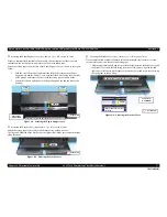
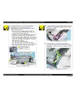
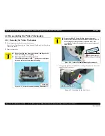
Figure 4-17. Connector layout of the Main Board
3.
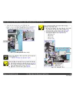
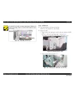
Peel off the four acetate tapes that secures the following cables on the back of
the Main Board Unit.
•
Power Supply Cable
•
CR Motor Cable
•
PF Motor Cable
•
PE Motor Cable
•
APG Sensor Cable
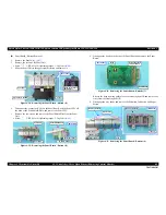
Figure 4-18. Removing the Main Board Unit (1)
Table 4-6. List of Connectors and their Destinations
CN No.
@
Color
Destination
Number of pins
CN3
White
P/S Assy
3pin
CN4
White
CDR Guide Sensor / CDR Tray Sensor
4pin
CN5
FFC
Panel Board
8pin
CN6
White
PE Sensor
3pin
CN7
Black
APG Sensor
3pin
CN8
FFC
PF Encoder
5pin
CN10
FFC
Head FFC
13pin
CN11
FFC
13pin
CN12
FFC
9pin
CN13
Black
PF Motor
2pin
CN14
White
CR Motor
2pin
CN15
FFC
CSIC Assy
13pin
CN6 CN7
CN3
CN4
CN15
CN5
CN8
CN17
CN13
CN10
CN11
CN16
CN14
CN12
Main Board Unit
CN16
FFC
PW Sensor / CR Encoder Sensor
6pin
CN17
White
Cover Open Sensor
2pin
Table 4-6. List of Connectors and their Destinations
CN No.
@
Color
Destination
Number of pins
Main Board Unit
Acetate Tape
Acetate Tape
Содержание 50 - Artisan 50 - Printer
Страница 8: ...Confidential C H A P T E R 1 PRODUCTDESCRIPTION ...
Страница 22: ...Confidential C H A P T E R 2 OPERATINGPRINCIPLES ...
Страница 29: ...Confidential C H A P T E R 3 TROUBLESHOOTING ...
Страница 52: ...Confidential C H A P T E R 4 DISASSEMBLY ASSEMBLY ...
Страница 103: ...Confidential C H A P T E R 5 ADJUSTMENT ...
Страница 120: ...Confidential C H A P T E R 6 MAINTENANCE ...
Страница 128: ...Confidential C H A P T E R 7 APPENDIX ...

