background image

RY

CM2

11

50

§

 max

DC 27Vmax

Open collector output

Run Signal [RUN]

When the [RUN] signal is selected as an intelligent output terminal, the inverter 
outputs a signal on that terminal when it is in the Run Mode.  The output logic
is active low, and is the open collector type (switch to ground)  

Option
Code

Terminal
Symbol

Function Name

Input
State

Description

0

RUN

Run signal

ON

OFF

when inverter is in Run Mode

Valid for inputs:
Required setting

C13

(none)

Notes:

¡

The inverter outputs the [RUN] signal 

    whenever the inverter output exceeds the 
    start  frequency . The start frequency is the
     initial inverter output  frequency when it
     turns on. 

Example:

when inverter Stop Mode

NOTE :

 The example circuit in the table above drives a relay coil.  Note the use

     of a diode to prevent the negative-going turn-off spike generated by the coil 
    from damaging the inverter's output transistor.

ON

DC braking

ON

Motor
speed

Run

signal

Run

command

FW[RV]

RUN

8-20

ENDA E-100


INSTRUCTION MANUAL

Содержание E-100 Series

Страница 1: ...dentifying the parts 5 Mounting 6 Wiring 7 Operation 8 Using Intelligent Input Terminals 9 Function List 10 Protective functions 11 Trouble shooting Tips 12 Maintenance and Inspection 13 Option 1 1 2...

Страница 2: ...th either of two signal words DANGER or CAUTION as described below DANGER Indicates a potentially hazardous situation which if not avoided can result in serious injury or death CAUTION Indicates a pot...

Страница 3: ...product This manual may be modified when necessary because of the improvement of the product modification or changes in specifications To order a copy of this manual or if your copy has been damaged o...

Страница 4: ...n bear the weight according to the specifications in the text Otherwise it may fall and cause injury to personnel Be sure to install the unit on a perpendicular wall which is not subject to vibration...

Страница 5: ...or fire Be sure to install the inverter in a well ventilated room which does not have direct exposure to sunlight a tendency for high temperature high humidity of dew condensation high levels of dust...

Страница 6: ...Implement wiring after checking that the power supply is off You may incur electric shock and or fire Do not connect wiring to an inverter or operate an inverter that is not mounted according the ins...

Страница 7: ...er supply to the output terminals U V W Otherwise there is the danger of injury and or fire Do not Run Stop operation by switching ON OFF electromagnetic contactors on the primary or secondary sides o...

Страница 8: ...ire Do not perform a withstand voltage test of the inverter Otherwise it may cause semi conductor elements to be damaged To connect a braking resistor braking resistor unit or braking unit follow the...

Страница 9: ...ng the trip reset Do not approach the machine be sure to design the machine so that safety for personnel is secure even if it restarts Otherwise it may cause injury to personnel and or fire If the pow...

Страница 10: ...the alarm reset after verifying the operation command is off Otherwise it may cause injury to personnel Be sure not to touch the inside of the energized inverter or to put any conductive object into...

Страница 11: ...anged from low speed to high speed Be sure check the capability and limitation of the motor and machine before operating the inverter If you operate a motor at a frequency higher than the inverter sta...

Страница 12: ...tools with insulated handles Otherwise there is a danger of electric shock and or injury to personnel Never touch high voltage terminals in the inverter Otherwise there is a danger of electric shock T...

Страница 13: ...on the main cover of the inverter as shown in the figure Follow these instructions when handling the inverter 1 12 Risk of electric shock Ensure proper earth connection Refer to the user s manual befo...

Страница 14: ...2 Motor Terminal Surge Voltage Suppression Filter In a system using an inverter with the voltage control PWM system a voltage surge caused by the cable constants such as the cable length especially wh...

Страница 15: ...supply changes are expected some examples Several inverters are interconnected with a short bus An installed leading capacitor opens and closes Note 5 RC Value of the thermal Relay is 1 1 times great...

Страница 16: ...w 015 S E 100 Series name Input voltage S single phase 200V class 2 Receiving and checking If any part of E 100 is missing or damaged call for service immediately 2 1 022 2 2kW 3HP 007 0 75kW 1HP 015...

Страница 17: ...current A Starting torque with sensorless vector control Dynamicbraking approx torque shorttimestop 5 with resistor from 50 60Hz without resistor DC braking Weight kg E 100 007S E 100 015S E 100 022S...

Страница 18: ...minal Volt Freq Characteristic Freq setting FWD REV Run Input signal Any base freguencysetting possible between0Hz and 400Hz V F control constant torque reducedtorque 150 60 seconds 0 1 to 3000sec lin...

Страница 19: ...aneouspower failure output short circuit detection AVR function curvedaccel decel profile upperand lowerlimiters 16 stagespeedprofile fineadjustment ofstartfrequency carrierfrequencychange 0 5 to 16Kh...

Страница 20: ...To operate the motor beyond 50 60Hz consult the motor mamanufacturer about the maximum allowable rotation speed 5 The braking torque via capacitive feedback is the average decelection torque at the sh...

Страница 21: ...ts Main Physical Features Colling fan Main circuit terminal Display part Communication port Control key Analog voltage current selection switch for frequency command Control circuit terminal 4 1 Ex E...

Страница 22: ...Inverter Dimensions for Mounting 4 2 External Dimension Type 007SF 015S 022S W 80 95 H 142 142 D 135 135 ENDA E 100 INSTRUCTION MANUAL H W D...

Страница 23: ...according to the specifications in the text Otherwise it may fall and cause injury to personnel CAUTION CAUTION Be sure to install the unit on a perpendicular wall which is not subject to vibration O...

Страница 24: ...inverter specified in the diagram Before proceeding to the wiring section it s good time to temporarily cover the inverter s ventilation openings It will prevent harmful debris such as wire clippings...

Страница 25: ...c fire and or injury to personnel Be sure not to connect an AC power supply to the output terminals Otherwise there is a danger of electric fire and or injury to personnel Be sure not to connect a res...

Страница 26: ...ter Power Motor Always connect the power input terminals L1 L2 to the power supply Be sure to install thermal relay individually when one inverter operates several motors Never connect P RB to R S T o...

Страница 27: ...frequency noise Install the AC reactor on the inverter output side or use the current sensor NOTE3 Make sure to ground the ground terminal according to the local grounding code Never ground the E 100...

Страница 28: ...speed2 Multi speed1 Reverse command Forward command Frequency meter Frequency command Note1 When an output intelligent terminal is used be sure to install a surge absorbing diode in parallel with rel...

Страница 29: ...h the extremely weak currents and voltages Note4 Use relays which do not have contact defects at 24 V DC 3mA for the other terminals Note5 Separate the main circuit wiring from the relay control circu...

Страница 30: ...CCB Magnetic contactor MC HBS 33 15AT HBS 33 20AT HBS 33 10AT HMC 10W HMC 20W HMC 10W 6 3 Application wiring apparatus options Determination of wire and Fuse size E 100 022S E 100 015S E100 007S 1 25...

Страница 31: ...is useful when harmonic suppression measures must be taken when the main power voltage unbalance rate exceeds 3 and the main power capacity exceeds 500kVA or when a sudden power voltage variation occ...

Страница 32: ...rminal 2 Note 6 Use 0 5mm wire for the control circuit terminal Classify the detective current of the earth leakage breaker depending on the total distance between the inverter and the motor Note1 Whe...

Страница 33: ...l function Signal 5 4 3 2 1 CM1 FM CM1 Input signal Monitor signal Forward run command FW Reverse run command RV multi speed commands1 4 CF1 4 2 stage accel decel 2CH Reset RS second control function...

Страница 34: ...l for frequency command Intelligent output terminal run status signal RUN frequency arrival signal FA1 set frequency arrival signal FA2 overload advance notice signal OL PID error deviation signal OD...

Страница 35: ...power supply is cut off for a short period of time the inverter may restart operation after the power supply recovers if the command to operate is active If a restart may pose danger to personnel so...

Страница 36: ...equipment damage 7 1 Before the powerup test Prior to the test run check the following 1 Make sure that the power lines L1 L2 and output terminals U V and W are connected correctly Otherwise there is...

Страница 37: ...230V 50 60Hz Motor Power supply Regenerative braking resistor Ground ACTION Digital operator control 1 Turn On the power supply by turning ON MCCB The POWER LED will illuminate 2 After checking that t...

Страница 38: ...Otherwise there is the danger of equipment damage NOTE1 1 Did the inverter trip during acceleration or deceleration 2 Were the rpm and frequency meter readings as expected If the over current or over...

Страница 39: ...put Terminal 1 5 RV 1 CF1 2 CF2 3 CF3 4 CF4 5 JG 6 2CH 7 FRS 8 2 stageacceler ation deceleration Theaccelerationordecelerationtimeis possibletochange consideringthesystem Free runstop Externaltrip Una...

Страница 40: ...nput Commonterminalforintelligentinputterminals Frequency command power terminal Frequency command common terminal Frequency commanding terminal current command Frequency commanding terminal voltage c...

Страница 41: ...in the RUN mode When the output current exceeds a preset value the OL terminal signal turns on When the PID loop error magnitude the preset value the OD terminal signal turns on The inverter alarm si...

Страница 42: ...This is dedicated indicator so that it cannot be used as a line speed The indicator accuracy after adjustment is about 5 Depending on the meter the accuracy may exceed this value signal 2 output curre...

Страница 43: ...in Run Mode motor stop Inverter is in Run Mode motor runs reverse Inverter is in Run Mode motor runs stop Valid for inputs Required setting C01 C02 C03 C04 C05 A02 01 Notes When theForwardRunand Rever...

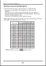
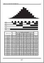
Страница 44: ...ON ON Multi Speed Select CF1 CF2 CF3 CF4 Theinverter provides storage parameters forup to 16 differenttarget frequencies speeds thatthe motor outputuses for steady staterun condition Thesespeeds area...

Страница 45: ...ON ON OFF OFF OFF OFF ON ON ON ON SW3 CF2 OFF OFF ON ON OFF OFF ON ON OFF OFF ON ON OFF OFF ON ON SW2 CF1 OFF ON OFF ON OFF ON OFF ON OFF ON OFF ON OFF ON OFF ON SW1 FW ON ON ON ON ON ON ON ON ON ON O...

Страница 46: ...tor function during each segment of a multispeed operation There are two ways to program the speeds into the registers to Programming using the CF switches Set the speed by following these steps 1 Tur...

Страница 47: ...otor jog is selectable by programming function The options are 0 Free run stop coasting 1 Deceleration normal level and stop 2 DC braking and stop Option Code Terminal Symbol Function Name Input State...

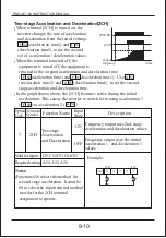
Страница 48: ...deceleration time2 to set the second stage acceleration and deceleration time In the graph shown above the 2CH becomes active during the initial acceleration This causes the inverter to switch form us...

Страница 49: ...s off The application determines which is the best setting Parameter specifies a delay time before resuming operation from a free run stop To disable this feature use a zero delay time B 03 FW RV FW R...

Страница 50: ...turned off the inverter remains in the trip state You must reset the inverter or cycle power to clear the error returning the inverter to the Stop Mode Option Code Terminal Symbol Function Name Input...

Страница 51: ...nal RS input or the keypad Stop reset key In the figure below the UPS feature is enabled When the inverter power turns on the motor does not start even though the Run command is already active Instead...

Страница 52: ...RS terminalinput theinverter restarts runningimmediately Evenwhenthetripstateis canceled by turningtheterminal RS onandoff after anunder voltageprotection E09 occurs theUSPfunction willbeperformed Wh...

Страница 53: ...e lock state or is locked as well Option Code Terminal Symbol Function Name Input State Description 11 SFT Software Lock ON OFF The keypad and remote program ming devices are prevented from changing p...

Страница 54: ...election switch exactly Option Code Terminal Symbol Function Name Input State Description 12 AT Analog Input Voltage current select ON OFF Terminal OI is enabled for current input uses terminal L for...

Страница 55: ...thefunctionoftheterminalisthesameas thatofthe reset terminal TheStop Resetkeyontheinverterisonlyoperationalforafewsecondsafter inverter powerup whenahand heldremoteoperatorisconnectedtotheinverter Ift...

Страница 56: ...the signal due to the open collector output Frequency Arrival FA2 lower graph uses thresholds for acceleration and deceleration to provide more timing flexibility than FA1 Parameter C21 sets the arriv...

Страница 57: ...eentheset frequency 0 5Hz to 1 5Hzis turned on Atthetimeofdeceleration an arrivalsignalat a frequencybetweentheset frequency 0 5Hz to 1 5Hzis turned on Thedelaytimeoftheoutputsignalis 60ms nominal Exa...

Страница 58: ...when inverter is in Run Mode Valid for inputs Required setting C13 none Notes Theinverter outputs the RUN signal whenever theinverter outputexceeds the start frequency Thestartfrequencyis the initial...

Страница 59: ...rcuits use open collector transistors and are active low Option Code Terminal Symbol Function Name Input State Description 3 OL Overload advance notice signal ON OFF when output current is more than t...

Страница 60: ...Terminal Symbol Function Name Input State Description 4 OD Output deviation for PID control ON OFF when PID error is more than the set threshold for the deviation signal Valid for inputs Required set...

Страница 61: ...put is set to normally closed NC a time delay occurs until the contact is closed when the power is turned on Therefore when the alarm contact out put is to be used set a delay of about 2 seconds when...

Страница 62: ...The required torque characteristic or speed control characteristic may not be maintained in case that the inverter capacity is move than twice the capacity of the motor in use Select the parameter A3...

Страница 63: ...verter finally set the parameter H01 F02 F03 setting Set the time the range that over current or over voltage trip event not occurs Set the same as setting F02 H03 setting Set the motor rating 1 007SF...

Страница 64: ...rocessfailed Motorconnection Auto tuningmode selectionH01 1 RuncommandON Motorparametersetting Parametersetting completed stop Note The motor parameter of E 100 is standard data of ENDA standard 4 pol...

Страница 65: ...stor R2 Transient inductance Motor inductance Settingrange 0 1 0 1 2 4 6 8 0 001 30 00 0 001 20 00 0 01 999 9 0 01 100 0 0 1 100 0 Description 0 auto tuningOFF 1 auto tuningON 0 standarddata 1 auto tu...

Страница 66: ...ning constants may be stored in the inverter It will be necessary to store the inverters factory defaults setting Powered running status with a accelerating torque Whenlow frequency afew Hz torqueis i...

Страница 67: ...the data and setting value to the memory Potentiometer set the inverter output frequency be operated only when the ramp is ON Hz A LED Display units Hertz Ampere LEDs STOP RESET key This key is used...

Страница 68: ...UN STOP RESET RUN key This key starts the run The set value of determines a forward run or a reverse run STOP RESET key This key stops the run When a trip occurs this key becomes the reset key basis s...

Страница 69: ...setting storedataandreturntotheexpanded command settingdataisdisabled donotstoredataandreturntotheexpanded command settingdataisdisabled Displaydescription Whentheinverteristurnedon theoutputfrequenc...

Страница 70: ...z Hz LED ON Real time display of output current to motor from 0 0 to 99 9A A LED ON Real time display of output voltage to motor Three different indications F Forward Run Stop r Reverse Run Displays t...

Страница 71: ...Inverter real operating time 0 59 Displays the inverter DC link voltage V Displays the current trip event Display method Alarm reason press the UP key Output frequency at alarm event press the UP DOW...

Страница 72: ...L OI L Frequency reference by the local potentiometer can be monitored Standard default acceleration setting range is 0 1 to 3000sec 0 1 999 9 by 0 1sec 1000 3000 by 1sec Standard default deceleratio...

Страница 73: ...mmunication Set the method of run commanding 0 Standard operator 1 Control circuit terminal input 2 Remote operator communication 0 0 60 00Hz Settable from the base frequency A03 up to 400Hz in units...

Страница 74: ...z Multi speed Frequncy Setting Multi speed frequency setting Jogging frequency setting Jogging stop operation selection A11 A25 A26 A27 Defines limited speed for jog range is 0 5 to 10 00Hz in units o...

Страница 75: ...ons 0 Manual torque boost 1 Automatic torque boost Two available V F curves three select codes 0 Constant torque 1 Reduced torque reduction of the 1 7th power 2 Sensorless vector control A32 V 100 20...

Страница 76: ...conds in units of 0 1sec DC braking frequency setting DC braking output delay time setting DC braking force setting DC braking function selection Frequency related Functions A38 A39 A40 A42 A44 0 00Hz...

Страница 77: ...le 1 PID control enable Derivative gain has a range of 0 0 to 100 0 seconds in units of 0 1 Automatic Voltage Regulation AVR Function A52 A53 0 220V 200V class inverter settings 200 220 230 240 400V c...

Страница 78: ...quency atwhichAccel1 switches toAcce12 rangeis 0 00to 400 0Hzinunits of0 01Hz frequency acc1 acc2 2CH time Two options for switching from 1st to 2nd accel decel 0 2CH input from terminal 1 transition...

Страница 79: ...put 1 10V input Set the voltage offset for external analog signal input input signal adjustment Set the voltage gain for external analog signal input signal adjustment Set the current offset for exter...

Страница 80: ...the gains as follows according to the symptom of the inverter The change of controlled variable is slow even when the target value is changed Increase P gain A47 The change of controlled variable is...

Страница 81: ...nd displaytripinfo Restarttripisovercurrent overvoltage and undervoltage Overcurrentandovervoltagetriprestart upto3times undervoltagetriprestart upto10time Theamountoftimeapower inputunder voltagecano...

Страница 82: ...deceleration rate when inverter detects overload range is 0 1 to 10 0 and resolution is 0 1 b07 b08 Motor Current Output frequency b04 b05 100 0 1 Electronic thermal characteristic selection Electroni...

Страница 83: ...Trip history clear 1 Parameter initialization Select how the inverter resumes opera tion when the free run stop FRS is cancelled two options 0 Restart from 0Hz 1 Restart from frequency detected from r...

Страница 84: ...r terminal 3 code see C01 parameter Select function for terminal 4 code see C01 parameter Select function for terminal 5 code see C01 parameter Select logic convention two option codes 0 normally open...

Страница 85: ...rrent monitor 2 output voltage monitor Select logic convention two option codes 0 normally open NO 1 normally closed NC Output Terminal Function Montor signal selection Output Terminal 11 a b contact...

Страница 86: ...rrival signal frequency setting PID deviation level setting Sets the overload signal level between 50 and 200 resolution is 0 1 0 5x Inverter rated current 2 0x Inverter rated current C20 Motor curren...

Страница 87: ...Sensorless Vector Control Auto tuning mode selection Motor data selection Motor capacity Motor poles setting Motor rated current Motor Resistance R1 Motor R2 Resistance Motor Inductance L Motor R2 Re...

Страница 88: ...put is cut off when communication in the inverter has an error to external noise excessive temperature rise or other factor When input voltage drops below the low voltage detection level the control c...

Страница 89: ...is not displayed when initialization of history is processing It is displayed when Copy function is operated by the remote operator There is no data available Trip history PID feedback data Display Th...

Страница 90: ...term inals H O and L connected to the potentiometer Is the motor load too heavy Is the motor locked Reduce load and test the motor independently Is the RS reset function or FRS free run stop function...

Страница 91: ...lem frequency Verify the V F settings match motor specifications Make sure all scaling is properly set Is the load too heavy Is the load fluctuation too great Is the supply voltage unstable Is the pro...

Страница 92: ...power turned off after a parameter edit but before pressing the store key Edits to data are permanently stored at power down Was the time from power off to power on less than six seconds Was the stand...

Страница 93: ...he unit clean so that dust of other foreign matter does not enter the inverter Take special care in regard to breaking wires of making connection mistakes Firmly connect terminals and connectors Keep...

Страница 94: ...uct the insulation resistance test by short circuiting the terminals as shown below Spare parts We recommend that you stock spare parts to reduce down time which include Part description Symbol Quanit...

Страница 95: ...easure between inverter terminals R S T Digital volt meter GND to terminals Torque wrench Thermal trip events Visual Visual Visual Visual Visual Visual Visual Aural Power down manually rotate Criteria...

Страница 96: ...meter Electronic type wattmeter Calculate the output power factor from the output voltage E output current I and output power W 0 0 0 Supply voltage E1 Output voltage E0 Supply current I1 Output I cur...

Страница 97: ...res below show measurement locations for voltage current and power measurements listed in the table on the previous page The voltage to be measured is the fundamental wave effective voltage The power...

Страница 98: ...ATTAGE WATTAGE 1 5 KW 2 2 KW 50 50 0 2 kW 0 3 kW 180 100 0 3 kW 0 3 kW 13 Option In case of Light load 13 1 ENDA E 100 INSTRUCTION MANUAL In case of Heavy load 1 2 Motor capacity kW Dynamic braking re...

Страница 99: ...tor has a 4 digit 7 segment LED so it is possible not only operate inverter but also display inverter status Specification Item Description External Dimension Keypad Communication Method Function Conn...

Страница 100: ...r The Run enable LED must be terminal operation UP DOWN key This key is used to change data and increase of decrease the frequency STORE KEY Press the store key to write the data and setting value to...

Страница 101: ...C reactor External Diagram Connection Diagram 13 4 ENDA E 100 INSTRUCTION MANUAL Power supply Reactor Inverter Motor ACL I Input side Out side put Inverter Reactor ACL I L1 L1 L1 L1 L 2 L 2 L 2 L 2 U...

Страница 102: ...crease when driving a general as compared with commercial power operation Connecting this reactor between the inverter and the motor allows reduction of motor pulsation When the cable between the inve...

Страница 103: ...90 95 100 115 120 110 130 130 130 130 190 40 50 50 50 50 60 52 67 70 72 90 80 6 6 6 6 6 6 4 4 4 4 4 4 1 85 3 0 3 4 3 9 5 2 8 6 1 1 1 1 1 1 200V 0 4 0 7 1 5 2 2 3 7 5 5 7 5 ACL L 0 4 ACL L 0 75 ACL L...

Страница 104: ...e Model Applicable inverter type 13 4 Noise filter Install a noise filter as shown in figure below The noise filte as close as possible to the inverter and its wiring distance minimized In addition th...

Страница 105: ...ber 3 Communication 2 Digital operator Item Interface Communication method Communication speed Communication code Data bits Parity Stop bit Starting method Wait time Connection type Error check RS485...

Страница 106: ...s as follows Frame start Frame start is recognized by signal line data transmitted Frame completion Frame completion is recognized by no data during correspond 4 5 character time Frame 1 Transmit from...

Страница 107: ...Higher 8bit of 16bit CRC Higher 8bit of 16bit CRC Lower 8bit of 16bit CRC Lower 8bit of 16bit CRC 1 byte 2 byte 2 byte 1 32 0 x 03 st 1 byte Group nd 2 byte Index st 1 byte 0 00 nd 2 byte N 0 01 0 08...

Страница 108: ...of 16bit CRC 1 byte 2 byte 2 byte 1 32 0 x 06 st 1 byte Group nd 2 byte Index Note1 Setting value Note 2 Communication number Order Parameter Data CRC Hi CRC Lo Communication number Command Parameter...

Страница 109: ...Group d C F S A H d st 1 byte st 1 trip nd 2 byte nd 2 trip 0x01 0x05 0x02 0x06 0x03 0x07 0x04 Trip information Previous first trip Previous second trip Previous third trip Trip count 0x01 0x01 0x01...

Страница 110: ...nd 2 byte Bit0 Forward command Bit1 Reverse command Bit2 Reset command Parameter value Conversion hexadecimal 60 00Hz st 1 byte 0x17 nd 2 byte 0x70 Communication data 6000 Parameter value Conversion...

Страница 111: ...exclusive OR of 16 bit register and 8 bit register 3 Shift right side 1bit 16 bit register 4 If the result of step 3 is 1 exclusive OR 16 bit register and 0xa001 5 Execute 8 times step 3 and step 4 6...

Страница 112: ...001 1000 0001 1111 1110 0100 0000 1111 1111 0010 0000 0111 1111 1 1010 0000 0000 0001 1000 0000 0111 1110 0000000 0 0 00 0 0 0000 0000000 00 0 0 00 00 0 0 0 0 0000 0000000 000 0 0 0 00 00 00 0 000 BIT...

Отзывы: