


56
EATON
www.eaton.com
Instruction Booklet
IB020003EN
Effective January 2021
AMPGARD RVSS
Reduced Voltage Soft-Starter
User Manual
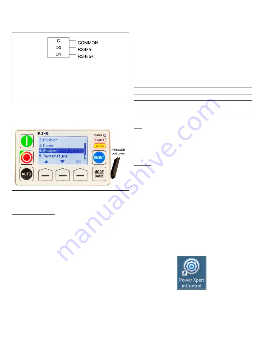
Figure 71.
Notes
• Shield shall be earthed externally
• Shield should NOT be connected to
any of these three terminals
• Wiring must meet PELV requirements
BCM RS-485 connections.
shows the micro USB port mounted on the right side of
the MUI.
Figure 72. MUI micro USB port
The BCM will be connected to the PC using either Modbus Serial
(RS-485) or Modbus TCP (Ethernet) communications.
Modbus communications
When the Modbus Serial interface is used, cable connections
between the BCM and the PC can be either
•
an Eaton cable
C445XS-USBMICRO
(USB A Male to Micro USB Male) for
connection between a PC and either the MUI right-side micro-USB port or the BCM
front micro-USB port, or
•
an Eaton cable
C445XS-USBLEADS
(USB A Male to flying leads cable) for
connection between a PC and the BCM bottom side RS485 serial port.
Configuration requirements are the same in either case (see
).
ote:
N
if the user does not have administrative rights and is having an IT
person install the inControl software, the USB/Micro USB cable needs to be
connected to a C445 during the installation for the USB driver to be installed.
If it is not connected at the time of installation, it must be installed later by
a person with administrator rights with the USB cable connected to a C445.
A driver for the USB/RS-485 cable must be installed on the
PC running the
inControl software for that cable to work with the software. The
driver for the Eaton cable may be found on the Eaton website.
ote:
N
be sure that the cable connection between the PC and the RVSS
controller is made before starting inControl and attempting to establish
communication between the PC and the controller.
Ethernet communications
When communicating using the Ethernet Module Ethernet port,
a Module port must be assigned and the port must be configured
through either the MUI or inControl. The BCM DIP switches on the
front (if used) are reserved for setting the Ethernet connection IP
address, whether as a static IP from the DIP switches, a dynamic IP
address from a host server, or a static IP address from internal BCM
storage. The MUI or inControl software can be used to determine
whether the DIP switches will be used or ignored.
9.3.6 Configuration: Modbus Serial (RS-485)
Communications can be established by configuring the BCM using
either inControl or the MUI. On the PC side, the serial connection
baud rate, data bits, parity and stop bits must be set to agree with
the BCM configuration (see
Table 14).
Table 14. Serial connection settings
Setting
Default
Range
Address
1
1 to 247
Baud rate
19200
9600, 19200, 115200
Stop bits
1
1 or 2
Parity
Even
Even or Odd
Mode
RTU
RTU or ASCII
MUI
To set up communications on the BCM side, use the MUI to select
PRG | Communications | Modbus.
From there you can set Modbus
Address (slave address), Modbus Baud Rate (19200, 9600, 38400,
57600, 115200), Modbus Transmit Mode (RTU or ASCII), Modbus
Parity (choose Even), Modbus Timeout (not needed).
Set up the PC side of communications following the procedure
shown below.
InControl
To prepare for PC communication with the BCM, connect a suitable
cable between the PC with inControl installed and the BCM. Use
one of the methods listed above.
ote:
N
It is important that the cable connection be made before starting
inControl, since inControl looks for connection possibilities only during its
startup. When the PC recognizes the presence of a connection, it assigns a
port to the link. InControl must be given that port assignment as part of its
communication configuration.
InControl records are called projects, saved as
*.efdt
files. When
starting up inControl, a previous project record can be opened,
or a new project record can be created. This section will describe
creating a new inControl project.
Start up inControl.
shows the inControl desktop icon.
shows the initial inControl screen. Use this screen
to create a project record, or to open an existing record. This
explanation will assume a
new
project must be set up, to connect to
an existing RVSS, previously configured (as shipped). If a new RVSS
needs configuration, use the inControl Setup Wizard or the MUI
Setup Wizard to do it.
Figure 73.
inControl desktop icon.


