


27
EATON
www.eaton.com
Instruction Booklet
IB020003EN
Effective January 2021
AMPGARD RVSS
Reduced Voltage Soft-Starter
User Manual
Section 5: Communication
5.1 Communication between BCM, I/O Board and MUI
The primary RVSS controller is located in the Base Control Module,
(BCM). The RVSS BCM has a CPU, local memory, a Real Time Clock,
and an Ethernet module installed. It has integral communications
interfaces for serial external communications and two local
communications channels located on the BCM bottom (see
). Local Channel 1 is connected to the Monitoring User Interface
(MUI) and provides bidirectional communication for system status
display and system parameter editing. Local Channel 2 is connected
to the I/O board. The I/O Board (IOB) provides digitized system
feedback of line voltage, output voltage, output current, and power
pole heat sink temperature. It also provides main and bypass
contactor status signals, start relay status, Reset input status and
Softstart SS2 Bypass Mode switch status to the BCM.
5.2 Communication using Modbus Serial
Modbus Serial can be used for local communication with externals
such as a PC for programming the BCM. In that case, since the
BCM has an Ethernet module installed, the Windows based
application programming interface app
inControl
must be used to
arrange the BCM' serial port parameters and the PC’s assigned serial
port address and configuration. This is because, when an Ethernet
module is installed, DIP switches on the BCM determine the IP
address for Ethernet port use, and cannot be used to set the BCM
serial communication parameters.
The BCM has serial communications requirements that a connected
PC must match. While the baud rate chosen has some options,
BCM defined stop bits, parity and transmission mode must
honored by the PC port configuration. The PC user setting up serial
communications with the BCM must have Windows Administrator
rights to use Windows Device Manager to set the port baud rate,
stop bits, parity and transmission mode. The PC can be cable
connected to the BCM using the BCM bottom RS-485 port or the
shows the RS-485 port. See
for the location of the BCM front micro USB port.
Figure 14.
Modbus
serial
port
(RS-485)
Bottom View
BCM
Setting Default Range
Address
1
1 to 247
Baud range 19.2K
9.6K, 19.2K, 115.2K
Stop bits 1
1 or 2
Parity
Even
Even or Odd
Mode
RTU
RTU or ASCII
Local Communications
Channels 1 and 2
BCM Modbus serial port.
The BCM can be connected to a PC using either
•
an Eaton cable
C445XS-USBMICRO
(USB A Male to Micro USB Male) for
connection between a PC and either the MUI right-side micro-USB port or the BCM
front micro-USB port, or
•
an Eaton cable
C445XS-USBLEADS
(USB A Male to flying leads cable) for
connection between a PC and the BCM bottom side RS485 serial port.
Since the PC port assignment has been determined by Windows
Device Manager, double-clicking on the inControl Modbus Serial
icon will invoke the Modbus Serial - Configuration tab. There
the PC chosen port assignment, baud rate, parity, stop bits, and
transmission mode can be set. Use Device Manager to be sure that
the chosen inControl settings are set in the Device Manager port
Properties Port Settings tab.
ote:
N
if the user does not have administrative rights and is having an IT
person install the inControl software, the USB/Micro USB cable needs to be
connected to a C445 during the installation for the USB driver to be installed.
If it is not connected at the time of installation, it must be installed later by
a person with administrator rights with the USB cable connected to a C445.
A driver for the USB/RS-485 cable must be installed on the
PC running the
inControl software for that cable to work with the software. The
driver for the Eaton cable may be found on the Eaton website.
ote:
N
be sure that the cable connection between the PC and the RVSS
controller is made before starting inControl and attempting to establish
communication between the PC and the controller.
5.3 Communication using Modbus TCP/Ethernet IP
The Base Control Module has a communications module receptacle
on its front that can accept an optional module for Ethernet for
Modbus/TCP and EtherNet/IP.
The BCM comes with the Ethernet module installed. The DIP
switches on the front of the MUI are used to set the IP address
method or value for the BCM. The Ethernet card IP address is set
using one of three methods (see
for DIP switch setting
guidance):
•
use the Ethernet card DIP switches to set a static IP lower octet,
192.168.1.
XXX
, (DIP 9 OFF)
•
use the DIP switches to enable DHCP, (DIP 9 ON, 1 ON)
•
use the DIP switches to enable setting a static IP using the MUI or
inControl,
then set it with either one (DIP 9 ON, 4 ON).
ote:
N
When configuring the Ethernet Card for network communication, be
sure to set the Ethernet Card subnet Mask to conform to the network subnet
mask.
ote:
N
Any changes to the communications settings will require a BCM
power down and power up to take effect.
For detailed information about the Ethernet card and its settings, see
MN042003EN, the Power XPert Global Motor Management Relay
User Manual.
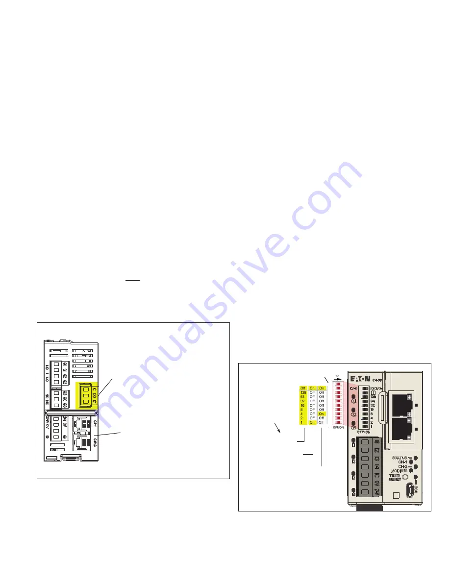
Figure 15.
Lo
w Oct
et (1
-254)
DHCP
Int
er
nal
IP A
ddfr
ess
Allocation
Meth
od
P1
P2
NS
MS
P1
P2
NS
MS
192.168.1.XXX
(0 - 253)
Reserved for future use
DHCP
Internal IP Address
Allocation Method
(Fixed, DHCP, or
NV Set using
inControl or MUI)
10
9
8
7
6
5
4
3
2
1
9 OFF = Lower Octet
9 ON, 1 ON
=
9 ON, 4 ON =
BCM DIP switches for IP address assignment.
For details on how to set up communication with the PC
inControl
.


