6
Installation and start-up
Radio Actuator KNX RF S1R-B2 compact
• Version: 16.09.2020 • Technical changes and errors excepted.
2.4. Connection
The
Radio Actuator KNX RF S1R-B2 compact
is installed in a flush-mounted sock-
et.
The connection to the
KNX data bus
is made via radio (KNX RF). The device is inte-
grated into the KNX system via a KNX RF USB stick or via a media coupler (refer to the
relevant manual/data sheet).
Connect the
operating voltage
(230 V AC, 50 Hz) to the “Power IN“ L/N terminals.
Connect
the drive or the loads
to the “OUT“ U
A
/A1/A2 terminals. The output is free
of potential and supplied with voltage U
A
.
To connect the
digital inputs
(fig. 1 no. 1) use the attached cable. The cables for the
inputs can be extendet to up to 10 m.
Follow the guidelines and standards for SELV electric circuits
while installing and cable laying of the inputs!
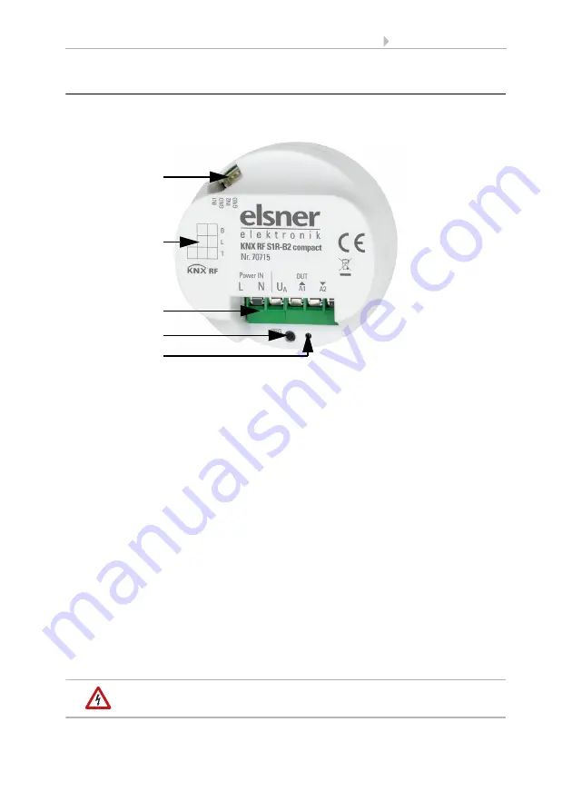
Fig. 1
1
Digital inputs: Slot for connection cable
2
Labelling field
3
Connector for operating „Power IN“ 230 V AC, 50 Hz, L/N
and for drive/consumers „OUT“(free of potential):
U
A
: voltage, maximum 270 V AC
up/A1: motor upwards or consumer 1 switching
down/A2: motor downwards or consumer 2 switching
4
Programming button (recessed)
5
Programming LED (recessed)
1
3
2
4
5


