XRGI
®
- INSTALLATION GUIDE
VERSION 1.0 2018
8
C
A B
15
16
17
18
9
8
10
12
13
14
11
C
A B
15
16
17
18
9
8
10
12
13
14
11
1
2
5
4
3 7
6
1
2
5
4
3 7
6
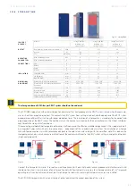
C O N S T R U C T I O N
Legend:
A
Electrical components and safety circuit
B
Air filter and mixture control
C
Sound- and heat-insulated engine compartment
1
Silencer (integrated)
2
Water-cooled generator
3
Exhaust gas cooler (not visible)
4
Oil sump
5
EC POWER gas engine
6
Oil separator
7
Catalyst (not visible (patented))
8
Primary circuit flow (1¼“ G)
9
Primary circuit return (1¼“ G)
10
Electrical connection
11
Exhaust gas connection (twin tube, di = 60 mm, da = 100 mm)
12
Gas connection: XRGI® 15: ¾“ G – XRGI® 20: ¾“ G
13
Air filter
14
Gas safety circuit
15
Cover with gas pressure springs
16
Spark plugs
17
Upright pipe for oil change
18
Oil filter (upright, water-cooled)
F U N C T I O N
C O N F I G U R AT I O N
The Power Unit contains the following main components:
■
Engine control
■
Cooling circuit
■
Mixture control
■
Engine electronics
■
Gas safety circuit
■
Temperature monitoring relay
Here, gas converts into electricity and heat.
The gas setting must only be carried out by authorised persons. This is described in the commissioning instruction. No further adjust-
ments are needed on the engine.
Fig. 2.08 - XRGI
®
15
Fig. 2.09 - XRGI
®
15
Fig. 2.10 - XRGI
®
15
Fig. 2.12 - XRGI
®
20
Fig. 2.13 - XRGI
®
20
Fig. 2.11 - XRGI® 20
Содержание XRGI 15
Страница 1: ...I N S T A L L A T I O N G U I D E 01DOC1043 VERSION 1 0 2018 FOR PROFESSIONALS ...
Страница 31: ...XRGI INSTALLATION GUIDE VERSION 1 0 2018 31 ...
Страница 61: ......
Страница 62: ...I N S T A L L A T I O N G U I D E FOR PROFESSIONALS ...


