XRGI
®
- INSTALLATION GUIDE
VERSION 1.0 2018
10
2
6
5
1
3
4
1
6
5
2
3
4
F U N C T I O N
C O N F I G U R AT I O N
The Q-Heat Distributor plays the following role in the XRGI® system:
■
Separation of the engine circuit (primary) from the heating
network
■
Protection of the primary circuit
■
Control of the engine temperature
■
Control of the system temperature
■
Management of the storage load
■
Management of the energy flows
The Q-Heat Distributor separates the engine circuit (Power Unit
cooling water circuit) from the heating system by means of a plate
heat exchanger. In this way, the expansion vessel protects the engine
circuit. The circulation pump for the engine circuit is mounted on the
left of the primary circuit of the Q-Heat Distributor. When the Q-Heat
Distributor is connected to power, the circulation pumps run for 5–10
seconds to check that they are working properly.
The pumps cannot be configured. They start together with the Power
Unit and stop approx. 10–20 minutes after the Power Unit has shut
down. Their power is controlled by the Q-Heat Distributor according
to demand. The storage charge group (on the right of the Q-Heat
Distributor) controls the engine temperature via the mixer and the
speed-controlled circulation pump. The system is designed to maximi-
se the storage charge temperatures (80–85 °C).
The Q-Heat Distributor does not need to be adjusted after assembly.
2.1.3
Q - H E AT D I S T R I B U T O R
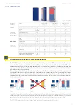
Legend:
1
Expansion vessel
2
RJ45 connector
3
Flow and return connection to the Power Unit
4
Flow and return connection to the storage tank/consumer network
5
Mixer for engine temperature control
6
Plate heat exchanger (not visible)
C O N S T R U C T I O N
Fig. 2.16 - Q20
Fig. 2.17 - Q80
Содержание XRGI 15
Страница 1: ...I N S T A L L A T I O N G U I D E 01DOC1043 VERSION 1 0 2018 FOR PROFESSIONALS ...
Страница 31: ...XRGI INSTALLATION GUIDE VERSION 1 0 2018 31 ...
Страница 61: ......
Страница 62: ...I N S T A L L A T I O N G U I D E FOR PROFESSIONALS ...


