XRGI
®
- INSTALLATION GUIDE
VERSION 1.0 2018
16
T1
T2
T3
T4
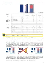
The control centre (central control of the virtual power plant) communicates the required operating strategy for the XRGI® system.
The XRGI® controller guarantees the operating mode (on, off or modulating mode) on the XRGI® system. Here, the storage tank plays
a key role and enables the management of the storage tank to be separated from the heat and the power production. The EC POWER
control individually defines the optimum mode of operation for each property based on:
■
level of the storage tank
■
actual heat demand
If no operating strategy is communicated by the control centre, the XRGI® system operates heat-controlled.
The EC POWER solution works on the basis of the operating status of the decentralised installed system and thus guarantees:
■
Simple and stable supply (without safety reserves for emergency heat demand)
■
Completion of the operating strategy by individual and selective emptying of the storage tank
■
No incorrect forecasts of the heat demand and the required expertise for this
■
Simple set-up of a virtual power plant at minimal cost
■
Fast achievement of an efficient virtual power plant even with smaller systems
SCOPE OF DELIVERY
Modules
VPP Gateway unit, one green system plug
DIMENSIONS
AND WEIGHT
Dimensions, W x H x D
mm
130 x 35 x 80
Weight
kg
0.165
The VPP Control is activated by means of potential-free contacts. This external control is independent of the manufacturer. For in-stan-
ce, it can be provided by the building’s own BMS, a small controller or a remote data transmission. The control voltage from the VPP
Control must be 24V and the cable cross-section must be 6 × 0.8 mm2. The control cable is connected to the VPP Control by the
supplied system plug (green).
The VPP Control is integrated into the Q-Network by the supplied CAT6 quality
RJ45 patch cable. A longer cable of the same quality can be provided on-site if the
supplied cable of 3 metres is not long enough. The VPP Control must be integrated
on the control side (i.e., the VPP Control can be connected either to the Power Unit
or to the iQ-Control Panel). Connection to the iQ-Control Panel is preferable.
O P E R AT I N G M O D E S
All the required functions needed for the operation of a virtual power plant can be provided with only
five operating modes.
SIGNAL 1: XRGI® system runs at „maximum“
The XRGI® system starts up when sensor T2 signals „cold“. It works until no further system cooling is pos-
sible (i.e., the engine constantly exceeds the outlet temperature of 95 °C).
SIGNAL 2: XRGI® system runs at „minimum“
The XRGI® system starts up when sensor T1 is „cold“. The controller tries to keep sensor T1 warm by swit-
ching between small load or modulating operation and maximum power. Thus, the XRGI® system largely
ensures the provision of heat without filling up the storage tank. The XRGI® system stops at the latest
when T1 signals „warm“.
SIGNAL 3: No production by the XRGI® system
The XRGI® system and one available electric heater, if fitted, remain switched off. The heat generation
must be ensured by an additional heat generator, controlled by a controller independent of the VPP.
SIGNAL 4: Electric heater runs at „minimum“
The electric heater starts up when sensor T1 is cold. The controller tries to keep the sensor T1 warm. Thus,
the electric heater largely ensures the provision of heat without filling up the storage tank.
SIGNAL 5: Electric heater runs at „maximum“
The electric heater starts up when sensor T2 signals „cold“. It works until the storage tank has been fully
charged.
2.2.1.5 V P P G AT E W AY
Abb. 2.25 - VPP Gateway
Fig. 2.27 - Electrical connection
Fig. 2.26
Содержание XRGI 15
Страница 1: ...I N S T A L L A T I O N G U I D E 01DOC1043 VERSION 1 0 2018 FOR PROFESSIONALS ...
Страница 31: ...XRGI INSTALLATION GUIDE VERSION 1 0 2018 31 ...
Страница 61: ......
Страница 62: ...I N S T A L L A T I O N G U I D E FOR PROFESSIONALS ...


