XRGI
®
- INSTALLATION GUIDE
VERSION 1.0 2018
35
4.4.1
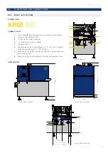
X R G I ® 6 / 9 - S Y S T E M
4.4
D I M E N S I O N S A N D C O N N E C T I O N S
1
32A CCE plug for generator cable 4 × 6 mm
2
to the iQ-Control Panel
2
Exhaust gas connection DN 60
3
1“ G flow to the Q-Heat Distributor
4
1“ G return to the Q-Heat Distributor
5
Gas connection ½“ G
6
Control cable to the iQ-Control Panel (1 × 2 × 0.75 mm
2
sh
earth) and network cable (1 × SFTP CAT6 RJ45)
7
Compartment for air filter, gas pressure controller, stepper motor and
gas mixture control
8
Compartment for the control board, safety circuit and ignition system
P O W E R U N I T
C O N N E C T I O N S
D I M E N S I O N S
4
3
1
6
8
7
5
2
960 mm
Max 110 mm
Min 60 mm
930 mm
79 mm
69 mm
640 mm
375
539
315
525
267
119
320
531
606
356
FIG. 4.02 - XRGI® 6/9
Fig. 4.03 - XRGI® 6/9 side view
Fig. 4.04 - XRGI® 6/9 top view
Fig. 4.05 - XRGI® 6/9 rear view
Содержание XRGI 15
Страница 1: ...I N S T A L L A T I O N G U I D E 01DOC1043 VERSION 1 0 2018 FOR PROFESSIONALS ...
Страница 31: ...XRGI INSTALLATION GUIDE VERSION 1 0 2018 31 ...
Страница 61: ......
Страница 62: ...I N S T A L L A T I O N G U I D E FOR PROFESSIONALS ...


