05/10
38
Inbetriebnahme des Modells
Getting started with the model
CCPM (Collective Cyclic Pitch Mix)-Steuerung
Die Funktionen Pitch, Roll, und Nick werden gleichzeitig von
drei Servos ausgeführt. Diese steuern im Abstand von 120° die
Stellung der Taumelscheibe und somit den Anstellwinkel der
Rotorblätter. Der Einfluss jedes einzelnen Servos ist dabei je
nach gewünschter Stellung der Taumelscheibe unterschiedlich
stark. Der Sender verfügt über eine entsprechende elektro-
nische Mischfunktion, der die Steuersignale für die einzelnen
Servos in Abhängigkeit von der Position der Steuerhebel / des
gewünschten Flugmanövers aufeinander abstimmt.
Flugvorbereitung
Für alle Richtungsangaben in dieser Anleitung
gilt:
Positionsangaben vorne / hinten / rechts / links
beziehen sich immer auf die Heli-Längsachse
in Flugrichtung “vorwärts” gesehen!
Stellen Sie sich genau hinter Ihren Helikopter (Flugrichtung
gleich Blickrichtung).
Solange Sie Ihr Modell von hinten sehen, reagiert Ihr Modell auf
die Steuerbefehle rechts, links, vor und zurück genau so, wie
Sie es sehen.
Wenn Ihr Modell jedoch mit der Kanzel zu Ihnen zeigt, reagiert
es genau entgegengesetzt, als Sie am Sender steuern.
Basiseinstellungen am Sender überprüfen
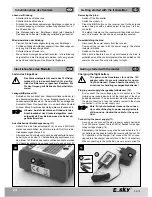
Position der Reverse-Schalter (22)
Die Reverse-Schalter bewirken eine Umkehr der
Funktionsrichtung. Die für den Flug benötigten Funktionsrichtungen
sind abhängig von der Einbaurichtung der Servos.
Im Auslieferungszustand des Senders müssen die folgenden
Einstellungen gewählt sein:
AIL
(Aileron, Querruder = Roll)
=
NOR
ELE
(Elevator, Höhenruder = Nick)
=
REV
THR
(Throttle, Gas = Gas/Pitch)
=
NOR
RUD
(Rudder, Seitenruder = Heck)
=
REV
Position des 3D-Schalters (23)
Der 3D-Schalter (Kippschalter 1) muss in der hinteren
Stellung stehen (Idle Up „OFF“).
In dieser Position ist der 3D-Modus abgeschaltet.
Im 3D-Modus gibt es keine Leerlaufstellung (Motor Aus). Wenn
der Gas/Pitch-Hebel beim Anstecken des Flugakkus am unteren
Endanschlag steht (Leerlaufstellung bzw. Motor Aus im nor-
malen Heli-Betrieb) würde der Hauptrotor also schlagartig auf
Höchstdrehzahl anlaufen.
Eine Schutzschaltung im Sender verhindert das
Anlaufen des Hauptrotors, wenn der 3D-Modus
beim Einschalten gewählt ist (Idle Up ON).
Es darf nur während des Fluges, aus der Mit-
telstellung des Gas/Pitch-Hebels in den 3D-Mo-
dus geschaltet werden!
Position der Steuerhebel und der Trimmschieber
Eine Schutzschaltung am 3 in 1 Regler verhindert das Anlaufen
der Rotoren, wenn der Gas/Pitch-Hebel nicht in Leerlauf/Motor-
Aus Stellung steht.
Bringen Sie den Gas/Pitch-Hebel in Leerlaufstellung, und die
Roll, Nick, und Heck-Hebel in Neutralstellung.
Die vier Trimmschieber müssen in der Mittelposition stehen.
CCPM (Collective Cyclic Pitch Mix) control
The Pitch, Aileron and Elevator functions are simultaneously
executed by three servos. These control the position of the
swash plate at a distance of 120° and thereby the angle of attack
of the rotor blades. The influence of every individual servo is
different depending upon the desired position of the swash plate.
The transmitter has a corresponding electronic mixing function,
whereby it coordinates the control signals for the individual
servos with one another depending upon the position of the
control lever / the desired flight manoeuvring.
Flight preparation
The following applies for all the direction speci-
fications in these instructions:
Position specifications to the front / back / right
/ left are always based on the longitudinal axis
of the helicopter as seen in the „forward“ flight
direction!
Stand exactly behind your helicopter (flight direction same
as the line of vision).
As long as you can see your model from behind, the latter will
react to the control commands: right, left, forward, backward
exactly as you see it.
Whereas, if the cockpit of the model points towards you, it reacts
exactly the opposite way from your steering commands at the
transmitter.
Check the basic settings on the transmitter
Position of the Reverse switch (22)
The Reverse switch reverses the functional direction. The func-
tional directions required for the flight depend upon the direction
of installation of the servos.
The transmitter must have the following settings when deli-
vered:
AIL
(Aileron = Roll)
=
NOR
ELE
(Elevator = Nick)
=
REV
THR
(Throttle = Gas/Pitch)
=
NOR
RUD
(Rudder = Heck)
=
REV
Position of the 3D switch (23)
The 3D switch (toggle switch1) must be in the rear position
(Idle Up „OFF“).
The 3D mode is switched off in this position.
There is no idle position in the 3D mode (Motor off). If the throttle
lever is in the lower limit position while inserting the flight battery
(idle position or Motor off in the normal helicopter operation), the
main rotor would also start suddenly at the highest speed.
A safety switch prevents the main rotor from
starting when the 3D mode is selected while
switching on the helicopter (Idle Up ON).
You should only change from the neutral posi-
tion of the throttle lever to the 3D mode while in
flight!
Position of the control levers and steering trims
A protective circuit in the 3-in-1 controller prevents the rotors
from starting up when the gas/pitch lever is not in the idle-run-
ning/motor-off position. Bring the throttle lever in the idle posi-
tion and the aileron, elevator and rudder levers in the neutral
position.
The four steering trims must be in the central position.

