05/10
50
Individuelle Einstellungen
Individual settings
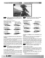
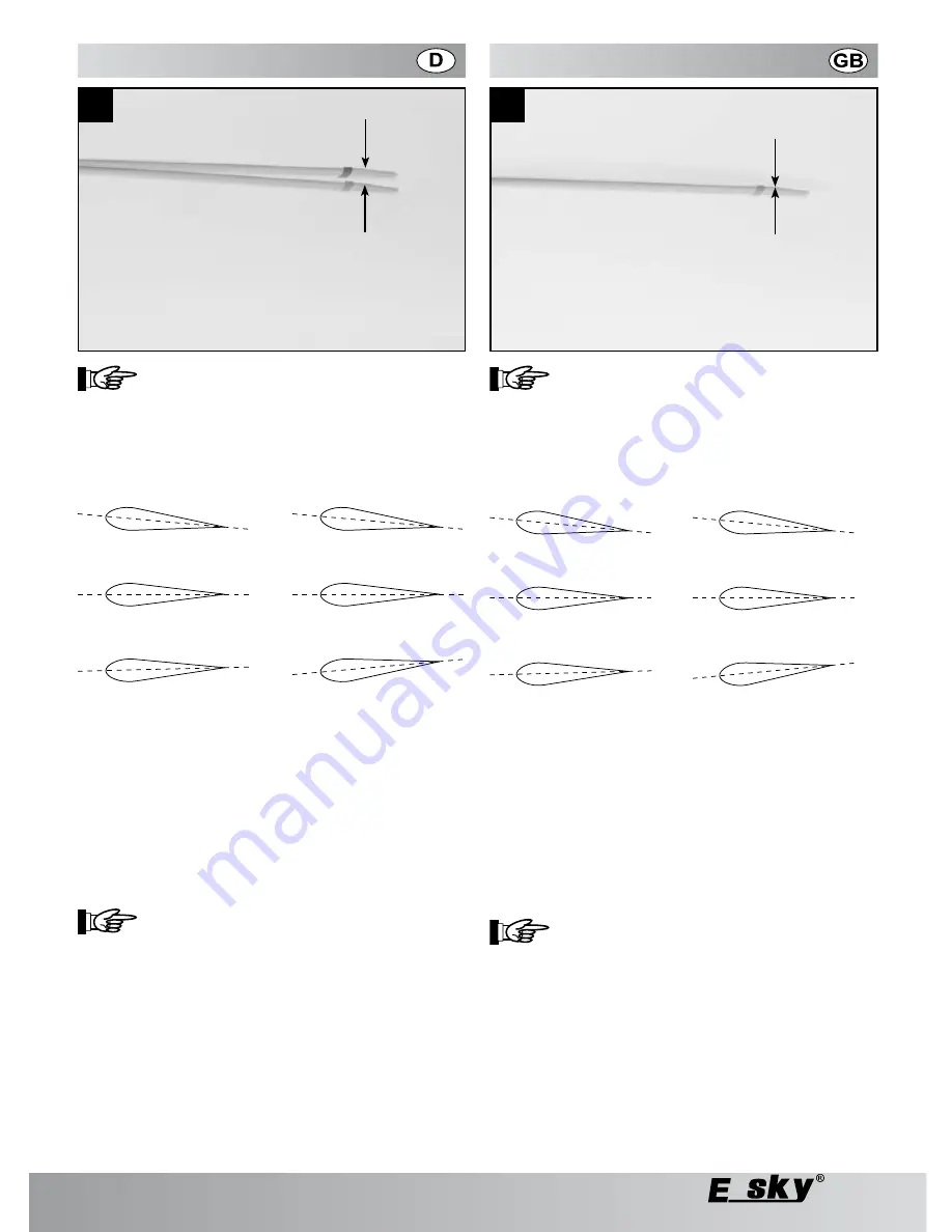
Überprüfen und korrigieren Sie den Spurlauf an
beiden Rotorblättern solange, bis beide Blätter
exakt in einer Ebene laufen.
Pitchwerte/Anstellwinkel Hauptrotor
Normalbetrieb
3D-Kunstflug
Gas/Pitchhebel MAX.
Gas/Pitchhebel MAX.
Anstellwinkel 6° - 7°
Anstellwinkel 6° - 7°
Gas/Pitchhebel Mitte
Gas/Pitchhebel Mitte
Anstellwinkel 0°
Anstellwinkel 0°
Gas/Pitchhebel MIN.
Gas/Pitchhebel MIN.
Anstellwinkel -2°
Anstellwinkel -7°
Ändern der Steuerhebelbelegung am Sender
Im Auslieferzustand des Senders finden Sie die Funktionen Gas/
Pitch und Heck auf dem linken Fernsteuerhebel, die Funktionen
Nick und Roll auf dem rechten Fernsteuerhebel.
Je nach persönlichem Bedarf können die Funktionen Roll und
Heck sowie die Funktionen Gas/Pitch und Nick durch Verstellen
zweier DIP-Schalter vertauscht werden. Da der Gas/Pitch-
Hebel nach dem Loslassen als einziger nicht automatisch in
die Mittelstellung zurückfedert, muss beim Vertauschen der
Gas/Pitch- und Nick-Funktion auch ein mechanischer Umbau
vorgenommen werden.
Dazu bedarf es der Erfahrung mit Fernsteuer-
sendern sowie technischem und handwerk-
lichem Geschick.
Umstellen der DIP-Schalter
Die DIP-Schalter befinden sich im Inneren des Senders und sind
nach Demontage der Senderrückwand zu erreichen (29).
Insgesamt können Sie zwischen vier unterschiedlichen
Steuerhebelbelegungen wählen, je nachdem ob Sie nur einen
oder beide DIP-Schalter verändern.
Im Auslieferungszustand stehen beide DIP-Schalter in der
unteren Position.
Entnehmen Sie zunächst die Batterien/Akkus aus dem
Batteriefach.
Schieben Sie den
linken DIP-Schalter nach oben:
-
-
Check and correct the pitch on both the rotor
blades till both the blades are in one plane.
Pitch / throttle values / angle of attack of the main
rotor
Normal operation
3D stunt flying
Throttle lever MAX.
Throttle lever MAX.
Angle of attack 6° - 7°
Angle of attack 6° - 7°
Throttle lever centre
Throttle lever centre
Angle of attack 0°
Angle of attack 0°
Throttle lever MIN.
Throttle lever MIN.
Angle of attack -2°
Angle of attack -7°
Changing the control lever assignment on the trans-
mitter
The transmitter, as delivered, has the throttle and rudder func-
tions on the left remote-controlled lever, and the aileron and
elevator functions on the right remote-controlled lever.
Depending upon the personal requirement, the aileron and rud-
der functions can be exchanged with the throttle and elevator
functions respectively by adjusting two DIP switches. Since
the throttle lever does not spring back automatically in the
neutral position, a mechanical restructuring is essential while
exchanging the throttle and elevator functions.
For this, you must have adequate experience
in handling remote-controlled transmitters as
well as technical skills.
Changing over the DIP switch
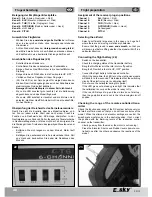
The DIP switches are located inside the transmitter and can be
accessed after removing the rear cover of the transmitter (29).
In all, you can select from four different control lever assign-
ments, depending upon whether you want to change only one or
both the DIP switches.
When the transmitter is delivered, both the DIP switches are
in the lower position.
First remove the batteries/accumulators from the battery
compartment.
-
26
27
28


