background image

User Manual for DEVO-12


  Page 10 of 238


11 

ELEV Trim 


27 

Throttle stick 


12 RUDD 

Trim 


28 AILE 

Trim 


13 Power 

SW 


29 ENT 


14 EXT 


30 R+ 


15 UP+ 


31 L- 


16 DN- 


32  


33 


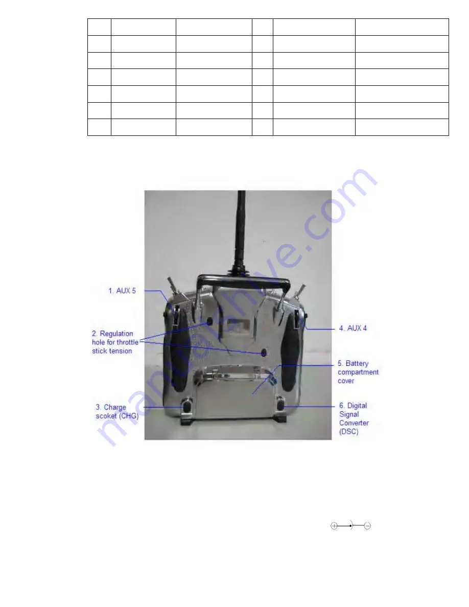
4.2 Rear definition 


1. AUX 

2.  Regulation holes for throttle stick tension. 

3.  Charge socket (CHG): input DC at 5V, 500-1000 mA; Polarity:

4. AUX 

Содержание DEVO-12

Страница 1: ...Neck strap usage 13 7 0 Stick mode switch 14 8 0 Switches between left hand and right hand throttles 16 8 1 Right hand throttle switched to left hand throttle 16 8 2 Left hand throttle switched to rig...

Страница 2: ...Rate and Exponential 65 3 5 Throttle hold 70 3 6 Throttle curve 72 3 7 Mix to throttle 74 3 8 Gyro sensor 75 3 9 Governor 77 3 10 Tail curve 78 3 11 Dual pitch 79 3 12 Swash mix 81 3 13 Pitch curve 8...

Страница 3: ...l 143 3 8 Differential 145 3 9 Balance 148 3 10 Gyro sensor 149 3 11 Governor 151 3 12 Aileron to Rudder Mix 152 3 13 Elevator to flap mix 153 3 14 Rudder to aileron elevator mix 154 3 15 Flap system...

Страница 4: ...3 4 Dual rate and exponential 209 3 5 Motor hold 212 3 6 Flaperon mix 213 3 7 Camber system 214 3 8 Differential 216 3 9 Balance 217 3 10 Gyro sensor 218 3 11 Rudder to spoiler mix 219 3 12 Aileron to...

Страница 5: ...ID assignment and also features customizedly fixed ID setup The usage of wireless copy function keeps you away from the trouble in wire link up Three mode types of Helicopter Airplane and Glider are a...

Страница 6: ...r maintain your equipment in order to assure its safety Please operate your equipment within the range of functions permitted It is forbidden to use out of the safety laws or regulations 4 Safety oper...

Страница 7: ...way 7 Ultra big size TFT touch screen with graphic interface features direct and convenient setting 8 Shape design accords with human engineering and provides comfortable holding 9 Both the length an...

Страница 8: ...micro computer system Frequency 2 4GHz DSSS Output power 100 mW Current drain 400 mA at 100 mW Power supply LiPo 3 7V 3 000 mAh Output pulse 1000 2000 mS 1500 Neutral 3 2 Receiver specification Type...

Страница 9: ...definition N O English Your language N O English Your language 1 Antenna 17 Hook eyelet 2 AUX 6 18 AUX 6 3 Throttle Hold 19 MIX 4 RUDD D R 20 TRN 5 GEAR 21 FMOD 6 ELEV D R 22 AILE D R 7 AUX 2 23 Righ...

Страница 10: ...EV Trim 27 Throttle stick 12 RUDD Trim 28 AILE Trim 13 Power SW 29 ENT 14 EXT 30 R 15 UP 31 L 16 DN 32 33 4 2 Rear definition 1 AUX 5 2 Regulation holes for throttle stick tension 3 Charge socket CHG...

Страница 11: ...partment cover 6 Digital Signal Converter socket DSC for simulator flight practice via computer You need software and its dongle which are available in hobby shops and for training 4 3 Wiring Diagram...

Страница 12: ...on mode 3 UP Function selecting key Move cursor up to the forward function item 4 DN Function selecting key Move cursor down to the next function item 5 R Move cursor rightwards to increase the settin...

Страница 13: ...tension of the corresponding stick by a Phillips screwdriver and counterclockwise rotate the stick tension screw for loosening the tension 6 0 Neck strap usage There is a concealable hook eyelet in th...

Страница 14: ...atus 3 Hook eyelet 7 0 Stick mode switch There are total four stick modes from MODE 1 through MODE 4 The left hand throttle includes MODE 1 and MODE 3 and the right hand throttle contains MODE 2 and M...

Страница 15: ...User Manual for DEVO 12 Page 15 of 238 2 Right hand stick includes MODE 1 and MODE 3 MODE 1 MODE 3 English Your language...

Страница 16: ...will be successful if both the MECHANICAL switch and ELECTRONIC switch are finished separately Below are the methods for switching 8 1 Right hand throttle switched to left hand throttle 1 MECHANICAL s...

Страница 17: ...or DEVO 12 Page 17 of 238 English Your language 1 Lateral non slipping block 2 Rear non slipping block 3 Remove the block from the semicircle hole Remove the fixed screws A1 A5 B1 B5 and then remove t...

Страница 18: ...Page 18 of 238 English Your language Base plate Remove the screws C1 and C2 Open the left and right switch caps respectively and then unscrew the screws C3 and C4 And remove the rear cover Note don t...

Страница 19: ...Throttle Control Spring in right throttle set respectively and then mount them in the corresponding positions in left throttle set And then adjust the stick tension according to your habit English Yo...

Страница 20: ...throttle switched to right hand throttle 1 MECHANICAL switch Refer to the above MECHANICAL switch to open the transmitter cover Below are shown the inside views of left and right throttle sets respec...

Страница 21: ...positions are shown respectively in the lower right corner when MODE 1 is selected The left and right stick positions are shown respectively in the lower right corner when MODE 3 is selected Touch to...

Страница 22: ...ters are exactly same Regarding the copying method refer to 2 4 Model Wireless Copy at Part Two Helicopter Then fallow the steps below 2 Linkage Insert one end of the signal wire into DSC socket at th...

Страница 23: ...ner s DEVO 12 English Your language DSC socket Two ends of digital signal wire Training status display when the trainer s icon becomes into X the trainee stops flying and the trainer is working when t...

Страница 24: ...worked with the TRN training lever which is located at the right top of DEVO 12 English Your language TRN training lever If the trainer s finger pulls the training lever TRN a is shown in the linkage...

Страница 25: ...below and the current status of trainer switch TRN is also shown English Your language Current status of Trainer Switch TRN SW The usable channels are shown here Touch the channel s which you desire t...

Страница 26: ...ished Below is the setting method Touch the icon to enter Model Menu and then enter Fixed ID by touching the icon in Model Menu English Your language Navigation mark Touch the navigation mark of the i...

Страница 27: ...random digits of ID Code English Your language Mini soft keyboard The new ID digits can be modified by touching the mini soft keyboard Touch Match after the new ID is already set An enquiry interface...

Страница 28: ...your transmitter system in your model Below are some advices on how to install your equipments 1 Wrap the receiver with 10mm thick foam and soundly fix it with a rubber or magic string on your aircraf...

Страница 29: ...s Antenna arranges in wrong directions 12 0 Installation requirement for DEVO 12 Battery pack Put the battery pack into the battery compartment in a correct position and then push it leftwards English...

Страница 30: ...n to use damaged battery pack The battery pack with electrolyte leaking or smelling should be away from fire in order to avoid firing or explosion He should be washed with water and sent to see a doct...

Страница 31: ...0mA Maximum current of USB interface 350mA 12 4 Indication for charging status There is a slim V shape indicator light at the top center of DEVO 12 It indicates three different working statuses from l...

Страница 32: ...ted the green light is extinguished if saturated 2 Charging at power off status 2 1 Charging indicator light blue light is always lighting 2 2 Power on indicator light red light is extinguished 2 3 Sa...

Страница 33: ...im 11 Dual rate exponential 2 Elevator trim 12 Model menu icon 3 PIT hover trim 13 Gyro sensor icon 4 Flight mode 14 System menu icon 5 Timer 15 Function menu icon 6 PIT percentage value 16 Model name...

Страница 34: ...Menu and then touch to enter the interface of Language Touch the language that you want to select A will be shown on the screen after selected Then touch to save and exit 1 2 Skin selection DEVO 12 o...

Страница 35: ...onsumption will be increased if the contrast is too high and the battery cruise duration will be shortened 3 Backlight lightness the backlight lightness is adjustable by touching the navigation marks...

Страница 36: ...n judge the position of the throttle stick according to the different musical scales It can also be set as Inhibit to silence the musical scales 3 Levers and knobs buzzer under the condition that this...

Страница 37: ...e possibility is that the power supply for the clock is not enough Replacing a new button cell is a must The method for changing button cell Turn off the power of your DEVO 12 and take off its battery...

Страница 38: ...6 TFT screen calibration Touch the icon to enter System Menu and then touch to enter the interface of TFT Screen Calibration Click anywhere on the screen to start calibration with the touch pen and t...

Страница 39: ...tick mode you desire and then touch the icon to exit 1 8 Stick and lever Touch the icon to enter System Menu and then touch the icon to enter the interface of Stick and Lever There are two items in th...

Страница 40: ...tick and left stick from their minimum levels to their maximum levels several times and then return the sticks to the neutral positions respectively 2 2 Lever calibration mechanically move the levers...

Страница 41: ...ier The transmission output power of DEVO 12 is adjustable It is divided into six grades from small to big The lower the transmission output power transmits the shorter the radio range is and the long...

Страница 42: ...rsions of hardware and software Click the icon to exit 2 0 Model menu Model Menu manages all the model data saved in DEVO 12 It includes Model Select Model Name Model Copy Model Transmit Model Receive...

Страница 43: ...esired name for your model for long term storage Its data can be directly withdrawn in next flights Repeat the step 2 1 Model Select to choose the model you want to name or save And then touch the ico...

Страница 44: ...up the old name English Your language Gray stripe Touch the soft keyboard to input a new name It is possible to switch between lowercase and uppercase by clicking the key Then touch to exit 2 3 Model...

Страница 45: ...d model name of Source Model will be shown in the left side of the interface Then touch the model in the right list where you want to locate the source model The serial No and name of the model you ch...

Страница 46: ...equipments can be wirelessly copied via Model Transmit and Model Receive in Model Menu 1 Model transmission Touch the icon to enter Model Menu and then continue to click the icon to enter Model Transm...

Страница 47: ...h the shortcut icon to enter Model Menu and then touch the icon to enter the interface of Model Receive Enquiry information Are you sure is shown in the center of the interface Click Ok for receiving...

Страница 48: ...matically return to Mode Menu Click Cancel for rejection Touch the icon to exit 2 5 Model reset All the model data can be restored to factory settings via Model Reset Touch the icon to enter Model Men...

Страница 49: ...mark to move the scroll bar and then choose the model you want to restore in the model name list All the selected model s name serial No and enquiry It is in use Are you sure will appear in the left...

Страница 50: ...nd Right Trim The trim range is divided into 20 grades factory default is set at 4 It is convenient to subtly modify the pitch by adjusting the trim range Touch the icon to enter Model Menu and then c...

Страница 51: ...r turn off position at which the stick stays can also be settable Method for setting Touch the icon to enter Model Menu and then click to enter Stick Position Switch Click the navigation mark of Switc...

Страница 52: ...annel Inhibit Elevator Aileron Throttle Rudder Choose the channel which will be set as switch At the same time Position and the status of turn on or turn off appear under the item Channel The current...

Страница 53: ...tion can set the warning for unsafety of which stick switch status or flight mode stays at the position while turning on the device or is used as start up warning in special purpose In factory Throttl...

Страница 54: ...is 0 0 when the throttle stick is at the lowest position Position is 100 0 when the throttle stick is at the highest position In factory Throttle Stick is set as Active Position in High direction at...

Страница 55: ...ode Main Switch 3 Stunt Trim Select There are two modes Common and Flight Mode In Common mode all the trim values which various sticks are corresponding to put equally effects on all the flight modes...

Страница 56: ...Setting method Touch the icon to enter Model Menu and then click to enter the interface of Device Output There are eight adjustable items They are Gear Pitch AUX2 AUX3 AUX4 AUX5 AUX6 and AUX7 respecti...

Страница 57: ...Pitch 2 Touch the desired item The default setting is Active English Your language Right column navigation mark Expansion list 1 Pitch The item is programmed as system default Any setting is unavaila...

Страница 58: ...t Active Gyro Governor and Pitch 2 Click the desired item The default setting is Active Then continue to set other items 3 AUX 3 Touch the left column navigation mark of AUX 3 and expands a list inclu...

Страница 59: ...overnor and Pitch 2 Choose the desired item The factory fault setting is Active Then continue to set up other items 4 AUX 4 Refer to 4 AUX 4 5 AUX 5 Refer to 4 AUX 4 6 AXU6 Refer to 4 AUX 4 Click the...

Страница 60: ...d ID This setting will bind DEVO 12 and its receiver in a unique corresponding relationship It will greatly speed up the time of automatic binding when DEVO 12 powered on 1 Setting for fixed ID The se...

Страница 61: ...k of the item ID Code Setting It will expand into two statuses Off and On A series of random digits will be shown below after touching On English Your language Touch On A series of random digits is sh...

Страница 62: ...already set An enquiry interface of Are you sure pops up ID Code Match will be shown after touching OK English Your language ID Code Setting ID Code Fixed ID Are you sure Cancelled ID Code Match 2 Fi...

Страница 63: ...atues On and Off Touch Off Then touch to exit 3 0 Function Menu Function Menu can help you make customizedly adjustments for the selected models The menu includes such items as Reverse Switch Travel A...

Страница 64: ...o increase or decrease the servo travel rang The adjustment range is from 0 0 to 150 0 The factory default is 100 0 Click the icon to exit 3 3 Sub Trim Sub Trim can parallel to move the neutral point...

Страница 65: ...ish Your language Channel name Adjustment range 1 Elevator D62 5 U62 5 2 Aileron R62 5 L62 5 3 Throttle L62 5 H62 5 4 Rudder R62 5 L62 5 5 Gear 62 5 62 5 6 Pitch L62 5 H62 5 7 AUX2 62 5 62 5 8 AUX3 62...

Страница 66: ...icon to enter Function Menu and then click to enter the interface of Dual Rate and Exponential 1 Channel selection Touch the navigation mark of Channel An expansion list pops up which contents Elevat...

Страница 67: ...y the corresponding dual rate switch among Pos 0 Pos 1 and Pos 2 Take the item Elevator at Channel as the example All the flight modes shown in the right column are set as Switch Then if we move the l...

Страница 68: ...ate If touching the navigation mark for just one item to amend the dual rate value the dual rate of the corresponding servo will be changed in one direction while the curve will being changed in one d...

Страница 69: ...dual rate value the dual rate of the corresponding servo will be changed in one direction while the curve will being changed in one direction at the right graph If touching the navigation mark for bot...

Страница 70: ...r to 3 5 Throttle Hold below Touch the flight mode that you want to set as automatic operation and an expansion list will be shown Click the desired position If Switch is selected it is only controlle...

Страница 71: ...item is impossible to be set The default setting is HOLD SW 2 Setting for Hold Position Touch the left navigation mark of the item Hold Position to decrease the position amount whose minimum is 20 0 t...

Страница 72: ...ount whose maximum is 100 0 Under the throttle hold turned on pull the throttle hold lever forward when moving the throttle stick to the point set by Cut Position from high position to low position th...

Страница 73: ...all the servos will be locked at the current status if click Cancel all the servos will not be locked at the current status Enter the following interface after clicking OK or Cancel 1 Adjustment for...

Страница 74: ...down with the changing of throttle trim So the throttle curve will being paralleled up or down with the movements of the seven points 3 Flight mode There are total five flight modes Normal Flight Stun...

Страница 75: ...he left or right navigation mark of Down to decrease or increase the mix amount when moving the throttle stick downwards The bigger the amount is the bigger the mix to throttle becomes Click the left...

Страница 76: ...lt setting is AUX 2 It is possible to alter into other channels by choosing in the item of Device Output refer to 2 11 Device Output 4 Gain adjustment There are total three levels for respective setti...

Страница 77: ...ht navigation mark of the flight mode which you want to automatically adjust to decrease or increase the amount of gyro gains respectively If the gyro you use has two modes of NOR or AVCS when the amo...

Страница 78: ...3 Stunt 4 and Throttle Hold Click the icon to exit after finished 3 10 Tail curve This function is mainly used for amending the reaction torque produced by pitch change of main rotor blades It is poss...

Страница 79: ...ion mark of Point and expand into nine points Click the point which you want to adjust 4 2 Status setting Touch the navigation mark of Status and expand into Inhibit and Active Click Inhibit for uncha...

Страница 80: ...al Pitch English Your language Dual pitch statuses will be shown at the upper right corner when moving the throttle stick Setting method Touch the icon to enter Function Menu and then click the icon t...

Страница 81: ...ted through altering the plus or minus sign before amount The adjustable range is 125 1 2 the mix amount setting for aileron stick moving to right touch the left or right navigation mark of the item R...

Страница 82: ...3 Stunt 4 the Flight Mode Extra Switch in Device Select should be chosen Refer to 2 10 Device Select and Throttle Hold Setting method Touch the icon to enter Function Menu and then click to enter Pit...

Страница 83: ...Click Active for changing its current amount with a dropdown of Output popped up 2 3 Output setting Touch the left or right navigation mark of Output to decrease or increase respectively the output a...

Страница 84: ...Select Their pitch curves can be separately set in their own flight modes The setting method is same as above Click the icon to exit after finished Below are shown several basic examples of Throttle c...

Страница 85: ...reely set the channels and amounts which you want to select and amend respectively Setting method Touch the icon to enter Function Menu and then click to enter the interface of Program Mix Eight Progr...

Страница 86: ...an enquiry All Servos Hold Click OK for all the servos will be locked at the current statuses click Cancel for unlocked Enter the next interface after clicking 1 Mater channel setting Touch the naviga...

Страница 87: ...d Touch left or right navigation mark of Up to decrease or increase separately the mix amount It is possible to reverse mix direction through changing the plus or minus sign before amount The adjustab...

Страница 88: ...Curve in Program Mix2 Touch the item Curve in Program Mix 1 and expands an enquiry All Servos Hold Click OK for all the servos will be locked at the current statuses click Cancel for unlocked Enter t...

Страница 89: ...hanging the plus or minus sign before the amount The adjustable range is 125 7 Switch Touch the navigation mark of Switch and expand a usable dropdown menu Select the desired switch and then click the...

Страница 90: ...as an example to explain Elevator setting Touch the item Elevator and expand a sub item in its right Click the left or right navigation mark to decrease or increase respectively the position amount w...

Страница 91: ...Model Wireless Copy B Linkage Insert one end of the signal wire into DSC socket at the rear face of the trainee s DEVO 12 and then turn on the power A linkage icon will be shown on the boot screen Fin...

Страница 92: ...ner s DEVO 12 English Your language DSC socket Two ends of digital signal wire Training status display when the trainer s icon becomes into X the trainee stops flying and the trainer is working when t...

Страница 93: ...ner is off C Usage method The training switch should be worked with the TRN training lever at the right top of DEVO 12 English Your language TRN training lever If the trainer s finger pulls the traini...

Страница 94: ...lable channels are shown below and the current status of trainer switch TRN is also shown English Your language Current status of Trainer Switch TRN SW All channels available to be used Touch the chan...

Страница 95: ...ck the icon to enter the interface of Timer A Setting for Timer 1 1 Timer 1 setting Touch the navigation mark of Timer 1 and expand a dropdown of Stopwatch and Countdown Select the desired timing meth...

Страница 96: ...Stick Position Switch 3 Set time The settable countdown time range is from 00 05 to 59 55 4 Interval This item offers the possibility to set the warning interval It will warn once every interval time...

Страница 97: ...enu The boot screen of airplane is shown as below N O English Your language N O English Your language 1 Elevator trim 11 Aileron trim 2 Flap trim 12 System menu icon 3 Flight mode 13 Function menu ico...

Страница 98: ...Language setting Touch the shortcut icon to enter System Menu and then touch to enter Language Touch the language that you want to select A will be shown on the screen after selected Then touch to sav...

Страница 99: ...D brightness by touching the navigation marks The power consumption will be increased if the LCD is too bright and will the battery cruise duration will also be shortened 7 LCD contrast the contrast c...

Страница 100: ...navigation mark at Buzzer Switch and pop up an alternative item Off and On If touching On a drop down menu is shown as the right upper 6 Throttle stick under Buzzer Switch is at the status of On if T...

Страница 101: ...tion marks respectively to make modifications Touch to save and exit Note if incorrect turn on time or production time appears one possibility is that the power supply for the clock is not enough Repl...

Страница 102: ...the button cell holder and the button cell will automatically pop up Replace the old cell with a new one Cell size CR 1220 3V English Your language Button cell holder Push outwards 1 6 TFT screen cali...

Страница 103: ...he calibration is finished 1 7 Stick mode Touch the icon to enter System Menu and then touch the icon to enter Stick Mode There are four stick modes from MODE 1 to MODE 4 Select the stick mode you des...

Страница 104: ...p 2 1 Stick calibration Clockwise or counter clockwise mechanically move the right stick and left stick from their minimum levels to their maximum levels several times and then return the sticks to th...

Страница 105: ...r amplifier The transmission output power of DEVO 12 is adjustable It is divided into six grades from small to big The lower the transmission output power transmits the nearer the radio range is and t...

Страница 106: ...get access to the interface of About You can check the versions of hardware and software Click the icon to exit 2 0 Model menu Model Menu manages all the model data saved in DEVO 12 It includes Model...

Страница 107: ...lick the icon to exit 2 2 Model name In the menu of Model Name you can make a desired name for your model for long term storage Its data can be directly withdrawn in the next flight Repeat the step 2...

Страница 108: ...Name and a gray stripe will be shown in the frame Touch the return key to clear up the old name English Your language Gray stripe Touch the soft keyboard to input a new name it is possible to switch...

Страница 109: ...e copied as source model The serial No and model name of Source Model will be shown in the left side of the interface Then touch the model in the right list where you want to locate the source model T...

Страница 110: ...equipments can be wirelessly copied via Model Transmit and Model Receive in Model Menu 3 Model transmission Touch the icon to enter Model Menu and then continue to click the icon to enter Model Transm...

Страница 111: ...ch the shortcut icon to enter Model Menu and then touch the icon to enter the interface of Model Receive Enquiry information Are you sure is shown in the center of the interface Click Ok for receiving...

Страница 112: ...ll automatically return to Mode Menu Click Cancel for rejection Touch the icon to exit 2 5 Model reset All the model data can be restored to factory settings via Model Reset Touch the icon to enter Mo...

Страница 113: ...tion mark to move the scroll bar and then choose the model you wants to restore in the model name list The selected model s name and serial No and enquiry It is in use Are you sure appear in the left...

Страница 114: ...nd right trim The trim range is covered from 1 to 20 grades factory default is set at 4 It is convenient to subtly modify the pitch by adjusting the trim range Touch the icon to enter Model Menu and t...

Страница 115: ...turn off position at which the stick stays can also be set up Method for setting Touch the icon to enter Model Menu and then click to enter Stick Position Switch Click the navigation mark of Switch It...

Страница 116: ...tch Switch Channel Inhibit Elevator Aileron Throttle Rudder Choose the channel which will be set as switch At the same time Position and the status of turn on or turn off appear under the item Channel...

Страница 117: ...set the warning for unsafety of which stick switch status or flight mode stay at the position while turning on the device or is used as start up warning in special purpose The factory default is set...

Страница 118: ...Position is 100 0 when the throttle stick is at the highest position The factory default setting is Throttle Stick is Active Position in High direction at 10 0 4 setting other items Other flight mode...

Страница 119: ...Flight Mode Main Switch 9 Stunt Trim Select There are two modes Common and Flight Mode In Common mode all the trim values to which various sticks are relative put equally effects on all the flight mo...

Страница 120: ...it or use other functions Setting method Touch the icon to enter Model Menu and then click to enter Device Output There are eight items to be adjustable They are Gear Pitch AUX2 AUX3 AUX4 AUX5 AUX6 an...

Страница 121: ...expansion including Inhibit Active Gyro Governor and Pitch 2 Touch the desired item The default setting is Active English Your language Right column navigation mark Expansion list 7 Flap There will sh...

Страница 122: ...Trim and Right Trim The default setting is Inhibit Select the desired item as the flap switch 2 2 If choose System it is impossible to set in Flap 3 AUX 2 Touch the left column navigation mark of AUX...

Страница 123: ...t Active Gyro Governor and Pitch 2 Click the desired item The default setting is Active Then continue to set other items 4 AUX 3 Touch the left column navigation mark of AUX 3 and expands a list inclu...

Страница 124: ...bit Active Gyro Governor and Pitch 2 Choose the desired item The factory fault setting is Active Then continue to set up other items 5 AUX 4 Refer to 4 AUX 4 6 AUX 5 Refer to 4 AUX 4 7 AXU6 Refer to 4...

Страница 125: ...Menu and then touch to enter the interface of Wing Type 1 Flaperon Touch the navigation mark of Wing Type and expand a dropdown menu with Normal Flaperon DELTA and 4 Aileron Choose the desired wing ty...

Страница 126: ...age 126 of 238 English Your language Left aileron Right aileron Connect to the output AUX1 in Receiver Connect to the output AILE in Receiver 1 2 DELTA Below is the sketch map of DELTA servo s assignm...

Страница 127: ...DELTA and 4 Aileron Click 4 Aileron Check the channel assignment by touching Monitor Refer to 3 19 Monitor The left aileron servos should be connected to the outputs GERA and AUX3 in the receiver and...

Страница 128: ...Output should be previously set as Inhibit when the AUX channel is being set Setting method 3 1 Channel selection Touch the navigation mark of Channel in the interface of Wing Type and expand into Ele...

Страница 129: ...e as above 4 Twin Engine This function can be set as twin engine output to meet the requirement for the models which are powered by twin engines 4 1 Mate setting Click the navigation mark of Mate and...

Страница 130: ...c binding when DEVO 12 powered on 1 Setting for fixed ID The setting for fixed ID should be under the status that automatic ID binding is successfully finished Below is the setting method Touch the ic...

Страница 131: ...keyboard is shown in the lower part after touching the random digits of ID Code English Your language Mini soft keyboard The new ID digits can be modified by touching the mini soft keyboard Touch Matc...

Страница 132: ...plug 5V DC power into other output terminal The red light of receiver will flash slowly This means the fixed ID code has been cancelled Pull out BIND PLUG DEVO 12 also needs to make relative cancellat...

Страница 133: ...Mix Flap System Aileron to Flaperon Mix Pitch Curve Program Mix Monitor Fail Safe Trainer and Timer 3 1 Reverse switch Touch the shortcut icon to enter Function Menu and then click the icon to enter...

Страница 134: ...efault setting is 100 0 Click the icon to exit after finished 3 3 Sub trim Sub Trim is used to make parallel movement of servos It is recommended to adjust the servo bell crank if the servo is far awa...

Страница 135: ...Left elevator D62 5 U62 5 AUX7 62 5 62 5 Note the model names shown will be different with the selected channels different Click the icon to exit after finished 3 4 Dual rate and exponential It is pos...

Страница 136: ...anual setting 3 Dual Rate adjustment It is possible to modify the value by touching the navigation mark of Dual Rate If touching the navigation mark for just one item to amend the dual rate value the...

Страница 137: ...of the corresponding servo will be changed in one direction while the curve will being changed in one direction at the right graph If touching the navigation mark for both items to amend the dual rate...

Страница 138: ...r to 3 5 Throttle Hold below Touch the flight mode that you want to set as automatic operation and an expansion list will be shown Click the desired position If Switch is selected it is only controlle...

Страница 139: ...item is impossible to be set The default setting is HOLD SW 2 Setting for Hold Position Touch the left navigation mark of the item Hold Position to decrease the position amount whose minimum is 20 0 t...

Страница 140: ...e hold turned on pull the throttle hold lever forward when moving the throttle stick to the point set by Cut Position from high position to low position the throttle enters the locked status That mean...

Страница 141: ...ch the navigation mark of Channel and expand a list including Left Throttle and Right Throttle Select the desired throttle which will be shown in Channel Channel will be shown in grey if Twin Engine i...

Страница 142: ...elow after choosing Active 6 Output setting Touch the left or right navigation mark of Output to decrease or increase respectively the output value The adjustable range is from 0 0 to 100 0 7 Throttle...

Страница 143: ...nd expand a dropdown menu including the selectable items in black Select the desired item whose left side will be changed into 1 from 0 If two items are selected And should be chosen Then touch the na...

Страница 144: ...ectively set the snap roll flight in the actions of left or right ascending or left or right descending The snap roll flying can be controlled by the Training lever or by setting the corresponding sti...

Страница 145: ...ing Type A Aileron differential setting Touch the shortcut icon to enter Function Menu and then click the icon to enter the interface of Differential Mounting servos in left and right ailerons are a m...

Страница 146: ...n mark to return Click the icon to exit after finished B Rudder differential setting V Tail should be previously set in Wing Type of Model Menu if the rudder differential function is activated Refer t...

Страница 147: ...ick the navigation mark to return Click the icon to exit after finished C Flap differential setting It should be previously set the flap dual channel function in Device Output at Model Menu refer to 2...

Страница 148: ...h are used in the dual channels It should be previously chosen one of the these wing types of Flaperon DELTA 4 Aileron and V Tail in Wing Type at Model Menu Refer to 2 12 Wing Type Setting method Touc...

Страница 149: ...ownward and a plus value means the amending direction is upward Click the icon to exit after finished 3 10 Gyro sensor This function offers the gain adjustment for gyro sensor which can be manually se...

Страница 150: ...amount respectively If the gyro you use has two modes of NOR or AVCS AVCS will be activated when the amount is above 50 0 The bigger the amount is the bigger the gyro sensor gain becomes The default...

Страница 151: ...ion of governor can be separately set in various flight modes For the absolute revolution amount please set in external governor The amount shown in DEVO 12 s governor is just a percentage for referen...

Страница 152: ...ing the symbol of plus or minus before the value The adjustable range is 125 Touch the left or right navigation mark of Right to change the value and the rightward mix value of aileron to rudder will...

Страница 153: ...em will be changed into 1 If two or more items are selected And should be selected Then touch the navigation mark to return back Click the icon to exit after finished 3 13 Elevator to flap mix This fu...

Страница 154: ...n Pos 0 and Pos 1 can be realized by setting the position of throttle stick Touch the left or right navigation mark of Throttle Stick to the position amount of throttle stick The default setting is In...

Страница 155: ...he adjustable range is 125 1 2 Pos 1 setting Setting is same as above 2 Aileron setting Setting is same as above 3 Throttle stick setting The switch between Pos 0 and Pos 1 can be realized by setting...

Страница 156: ...s on elevator It is possible to set three statuses of elevator and three statuses of flap respectively through three way flap control switch Setting method Touch the icon to enter Function Menu and th...

Страница 157: ...evator 3 Auto land Touch the navigation mark of Auto Land and expand a dropdown menu including Inhibit and Active If select Active another sub menu Throttle will be shown under Auto land 3 1 Throttle...

Страница 158: ...ol of landing Click the icon to exit 3 16 Aileron to flap mix This function can execute the mix of aileron to flap and can also be set as switch The flap dual channels should be previously set in Wing...

Страница 159: ...the position of throttle stick Touch the left or right navigation mark of Throttle Stick to the position amount of throttle stick The default setting is Inhibit The adjustable range is 0 0 100 0 4 Swi...

Страница 160: ...the interface will show the current used channel and the current position statuses of switches 1 Position setting Touch the navigation mark of Position and expand a sub menu with Pos 0 and Pos 1 Choos...

Страница 161: ...n mark of Output to decrease or increase respectively the output value The adjustable range is 100 6 Throttle stick setting The throttle stick can be set as a switch by touching the navigation mark of...

Страница 162: ...ent statuses are shown the factory default setting is Inhibit Take Program Mix 1 as an example to show how to use A Setting method for Normal in Program Mix 1 Touch the item Normal in Program Mix 1 an...

Страница 163: ...rd Touch left or right navigation mark of Up to decrease or increase separately the mix amount It is possible to reverse mix direction through changing the plus or minus sign before amount The adjusta...

Страница 164: ...Curve in Program Mix2 Touch the item Curve in Program Mix 1 and expands an enquiry All Servos Hold Click OK for all the servos will be locked at the current statuses click Cancel for unlocked Enter t...

Страница 165: ...changing the plus or minus sign before the amount The adjustable range is 125 14 Switch Touch the navigation mark of Switch and expand a usable dropdown menu Select the desired switch and then click t...

Страница 166: ...as an example to explain Elevator setting Touch the item Elevator and expand a sub item in its right Click the left or right navigation mark to decrease or increase respectively the position amount w...

Страница 167: ...Model Wireless Copy B Linkage Insert one end of the signal wire into DSC socket at the rear face of the trainee s DEVO 12 and then turn on the power A linkage icon will be shown on the boot screen Fin...

Страница 168: ...iner s DEVO 12 English Your language DSC socket Two ends of digital signal wire Training status display when the trainer s icon becomes into X the trainee stops flying and the trainer is working when...

Страница 169: ...ner is off C Usage method The training switch should be worked with the TRN training lever at the right top of DEVO 12 English Your language TRN training lever If the trainer s finger pulls the traini...

Страница 170: ...lable channels are shown below and the current status of trainer switch TRN is also shown English Your language Current status of Trainer Switch TRN SW All channels available to be used Touch the chan...

Страница 171: ...ick the icon to enter the interface of Timer A Setting for Timer 1 7 Timer 1 setting Touch the navigation mark of Timer 1 and expand a dropdown of Stopwatch and Countdown Select the desired timing met...

Страница 172: ...tick Position Switch 9 Set time The settable countdown time range is from 00 05 to 59 55 10 Interval This item offers the possibility to set the warning interval It will warn once every interval time...

Страница 173: ...uch the icon to exit after finished Part four Glider 1 0 System menu N O English name Your language N O English name Your language 1 Elevator trim 10 2 Flap trim 11 3 Flight mode 12 4 Timer 13 5 Flape...

Страница 174: ...then touch to enter Language Touch the language that you want to select A will be shown on the screen after selected Then touch to save and exit 1 2 Skin selection DEVO 12 offers three skins for your...

Страница 175: ...ontrast is too high and the battery cruise duration will be shortened 13 Backlight lightness the backlight lightness can be adjustable by touching the navigation marks The power consumption will be in...

Страница 176: ...ge the position of the throttle stick according to the different musical scales It is can be set as Inhibit 11 Levers and knobs under the condition that this item is set as Active DEVO 12 will sound w...

Страница 177: ...one possibility is that the power supply for the clock is not enough Replacing a new button cell is a must The method for changing button cell Turn off the power of your DEVO 12 and take off its batt...

Страница 178: ...utwards 1 6 TFT screen calibration Touch the icon to enter System Menu and then touch to enter TFT Screen Calibration Click anywhere on the screen to start calibration with the touch pen and then foll...

Страница 179: ...tick mode you desire and then touch the icon to exit 1 8 Stick and lever Touch the icon to enter System Menu and then touch the icon to enter Stick and Lever There are two items in the interface Stick...

Страница 180: ...k and left stick from their minimum levels to their maximum levels several times and then return the sticks to the neutral positions respectively 2 2 Lever calibration mechanically move the levers of...

Страница 181: ...put power of DEVO 12 is adjustable It is divided into six grades from small to big The lower the transmission output power transmits the nearer the radio range is and the longer the stand by time will...

Страница 182: ...oftware Click the icon to exit 2 0 Model menu Model Menu manages all the model data saved in DEVO 12 It includes Model Select Model Name Model Copy Model Transmit Model Receive Model Reset Type Select...

Страница 183: ...for your model for long term storage Its data can be directly withdrawn in the next flight Repeat the step 2 1 Model Select to choose the model you want to name or save And then touch the icon to exi...

Страница 184: ...up the old name English Your language Gray stripe Touch the soft keyboard to input a new name it is possible to switch between lowercase and uppercase by clicking the key Then touch to exit 2 3 Model...

Страница 185: ...nd model name of Source Model will be shown in the left side of the interface Then touch the model in the right list where you want to locate the source model The serial No and name of the model you c...

Страница 186: ...equipments can be wirelessly copied via Model Transmit and Model Receive in Model Menu 5 Model transmission Touch the icon to enter Model Menu and then continue to click the icon to enter Model Transm...

Страница 187: ...ch the shortcut icon to enter Model Menu and then touch the icon to enter the interface of Model Receive Enquiry information Are you sure is shown in the center of the interface Click Ok for receiving...

Страница 188: ...ll automatically return to Mode Menu Click Cancel for rejection Touch the icon to exit 2 5 Model reset All the model data can be restored to factory settings via Model Reset Touch the icon to enter Mo...

Страница 189: ...tion mark to move the scroll bar and then choose the model you wants to restore in the model name list The selected model s name and serial No and enquiry It is in use Are you sure appear in the left...

Страница 190: ...nd right trim The trim range is covered from 1 to 20 grades factory default is set at 4 It is convenient to subtly modify the pitch by adjusting the trim range Touch the icon to enter Model Menu and t...

Страница 191: ...turn off position at which the stick stays can also be set up Method for setting Touch the icon to enter Model Menu and then click to enter Stick Position Switch Click the navigation mark of Switch It...

Страница 192: ...tch Switch Channel Inhibit Elevator Aileron Throttle Rudder Choose the channel which will be set as switch At the same time Position and the status of turn on or turn off appear under the item Channel...

Страница 193: ...set the warning for unsafety of which stick switch status or flight mode stay at the position while turning on the device or is used as start up warning in special purpose The factory default is set...

Страница 194: ...Position is 100 0 when the throttle stick is at the highest position The factory default setting is Throttle Stick is Active Position in High direction at 10 0 6 setting other items Other flight mode...

Страница 195: ...1 Flight Mode Main Switch 15 Stunt Trim Select There are two modes Common and Flight Mode In Common mode all the trim values to which various sticks are relative put equally effects on all the flight...

Страница 196: ...it or use other functions Setting method Touch the icon to enter Model Menu and then click to enter Device Output There are eight items to be adjustable They are Gear Pitch AUX2 AUX3 AUX4 AUX5 AUX6 an...

Страница 197: ...expansion including Inhibit Active Gyro Governor and Pitch 2 Touch the desired item The default setting is Active English Your language Right column navigation mark Expansion list 8 Flap There will sh...

Страница 198: ...Trim and Right Trim The default setting is Inhibit Select the desired item as the flap switch 2 2 If choose System it is impossible to set in Flap 9 AUX 2 Touch the left column navigation mark of AUX...

Страница 199: ...t Active Gyro Governor and Pitch 2 Click the desired item The default setting is Active Then continue to set other items 10 AUX 3 Touch the left column navigation mark of AUX 3 and expands a list incl...

Страница 200: ...ibit Active Gyro Governor and Pitch 2 Choose the desired item The factory fault setting is Active Then continue to set up other items 11 AUX 4 Refer to 4 AUX 4 12 AUX 5 Refer to 4 AUX 4 13 AXU6 Refer...

Страница 201: ...Select the desired wing type The default setting is Inhibit 2 Tip Ailerons setting The setting is same as the above 3 Dual Spoilers setting The setting is same as the above 4 Dual channels setting It...

Страница 202: ...f Channel and expand a popup including Elevator Rudder and Flap Click the desired item 4 2 Mate setting Touch the navigation mark of Mate and expand a popup with Inhibit and the items shown in Device...

Страница 203: ...on to exit 2 13 Fixed ID This setting will bind DEVO 12 and its receiver in a unique corresponding relationship It will greatly speed up the time of automatic binding when DEVO 12 powered on 3 Setting...

Страница 204: ...rk of the item ID Code Setting It will expand into two statuses Off and On A series of random digits will be shown below after touching On English Your language Touch On A series of random digits is s...

Страница 205: ...lready set An enquiry interface of Are you sure pop up ID Code Match will be shown after touching OK English Your language ID Code Setting ID Code Fixed ID Are you sure Cancelled ID Code Match 4 Fixed...

Страница 206: ...statues On and Off Touch Off Then touch to exit 3 0 Function menu Function Menu is used to make personalizedly fine adjustment to the selected models It includes Reverse Switch Travel Adjust Sub Trim...

Страница 207: ...icon to exit after finished 3 2 Travel adjust Touch the icon to enter Function Menu and then click the icon to enter the interface of Servo Adjust The interface contents two pages to show the current...

Страница 208: ...o enter the interface of Sub Trim Touch the navigation mark of the desired item to adjust the amount for rectifying the servo s neutral point The default neutral point is set at 0 0 The adjustment ran...

Страница 209: ...arious parameters which are suitable for yourself Setting method Touch the icon to enter Function Menu and then click the icon to enter the interface of Dual Rate and Exponential 1 Channel selection T...

Страница 210: ...ual rate of the corresponding servo will be changed while the curve will being changed at the same time shown at the right graph The default setting is 100 English Your language Upper curve Lower curv...

Страница 211: ...ed at the same time shown at the right graph The default setting is Line Then touch this mark to return to the interface of Dual Rate and Exponential 5 Automatic setting Under working with Flight Mode...

Страница 212: ...R lever Click the icon to exit 3 5 Motor hold The motor hold can be switched after the function is used The setting range of motor hold is from 10 to 100 This function should be previously set the ite...

Страница 213: ...you want and a will be shown in its left If two or more switches are chosen the item And should be selected Touch the icon to exit 3 6 Flaperon mix This function is used to mix Aileron to Flaperon or...

Страница 214: ...e navigation mark of Up or Down to change the Flaperon mix value when moving the Flaperon stick The bigger the value is the bigger mix is The adjustable mix is ranged from 125 to 125 It is possible to...

Страница 215: ...elect before using this function refer to 2 10 Device Select Touch the navigation mark of Flight Mode and expand a popup where you can select the desired flight mode 2 L or R Aileron setting Touch the...

Страница 216: ...of L or R aileron with a range of 100 It is possible to alter the direction of L or R aileron via changing the character of R or L before the amount Click the icon to exit 3 8 Differential 1 Flight m...

Страница 217: ...should be previously set at Tip Aileron in Model Menu refer to 2 12 Wing Type Touch the left or right navigation mark of Tip Aileron to decrease or increase respectively the value with a range of 100...

Страница 218: ...etting is 0 The minus value means the amending direction is downward and the plus value means upward Click the icon to exit 3 10 Gyro sensor This function offers the gain adjustment for gyro sensor It...

Страница 219: ...50 0 If a gyro with NOR and AVCS is used NOR will work when the value is less than 50 0 and AVCS will work when the value is more than 50 0 Touch the icon to exit 3 11 Rudder to spoiler mix When this...

Страница 220: ...the default setting is 0 0 Touch the icon to exit 3 12 Aileron to rudder mix This function aims at mixing the rudder when operating the aileron The mix value can be respectively set in each flight mod...

Страница 221: ...lue with a range of D1 100 When the elevator stick is moved down from this value the mix will be cancelled while the elevator stick is moved up from this value the mix will be activated The default se...

Страница 222: ...navigation mark of Up in the flight mode you desire to change the mix value of elevator to flap when moving the elevator stick upwards It is possible to alter the mix direction via changing the sign...

Страница 223: ...evice Select Touch the navigation mark of Left in the flight mode you desire to change the flap mix value when moving the aileron stick leftward It is possible to alter the mix direction via changing...

Страница 224: ...efore the value The adjustable mix value is 125 The default setting is 100 Touch the navigation mark of Right in the flight mode you desire to change the flap mix value when moving the aileron stick r...

Страница 225: ...tion mark of Down to change the flap rate when flap moving downward It is possible to alter the direction by changing the sign before the value The adjustable range is 125 and the default setting is 0...

Страница 226: ...Brake to Spoiler The brake mix at Pos 0 will be altered through touching the navigation mark of Pos 0 at Spoiler to change the value The adjustable value is 0 0 100 and the default setting is 100 0 Th...

Страница 227: ...18 Program mix There are total eight sets of Program Mix It is possible to freely set the channels and amounts which you want to select and amend respectively Setting method Touch the icon to enter F...

Страница 228: ...k Cancel for unlocked Enter the next interface after clicking 7 Mater channel setting Touch the navigation mark of Master and expands a selectable dropdown menu After clicking the desired channel the...

Страница 229: ...is function can make Slave begin to mix through switch from a certain point as the starting point Touch the left or right navigation mark of Offset to decrease or increase respectively the mix amount...

Страница 230: ...ed if choosing On Otherwise choosing Off 18 Point Touch the navigation mark of Point and expand a dropdown menu with nine points Click the point you want to set and then touch the navigation mark to r...

Страница 231: ...erface of Monitor for checking the current working status of each channel Click to the icon exit after finished 3 20 Fail safe There are two possibilities for use if the transmission signal is under a...

Страница 232: ...the icon to exit after finished Note checking whether all the actions when fail safe happened are correct is a must after the setting is finished It is dangerous to use full throttle especially after...

Страница 233: ...boot screen Find out the trainee s model data English Your language Linkage icon at trainee s icon Turn on the power of the trainer s DEVO 12 Find out the trainee s model data and let the trainer s D...

Страница 234: ...signal wire Training status display when the trainer s icon becomes into X the trainee stops flying and the trainer is working when the trainer s icon turns into the trainee is flying and the trainer...

Страница 235: ...his finger from the trainer lever an X will be shown there Setting for training function channels Trainee is available to get full or part of flight control power to the aircraft model via setting the...

Страница 236: ...ire to grant to trainee The channel s you have touched will be activated as Active The channels which are not granted to trainee keep inhibited The default setting is Inhibit Touch to save and exit af...

Страница 237: ...1 setting Touch the navigation mark of Timer 1 and expand a dropdown of Stopwatch and Countdown Select the desired timing method The timing range of stopwatch is from 0 to 59 59 59 minutes 59 seconds...

Страница 238: ...g interval It will warn once every interval time The adjustable range is from 00 05 to 05 00 The default setting is Inhibit 17 Down alarm It is possible to set the down alarm in countdown The setting...

Страница 239: ...G G G G G G G G G G G...

Отзывы: