- 37 -
MOUNTING THE CASE
Mounting of the relay case on the prepared panel is done as described below.
1.
Open the relay cover; preferably drive out the internal unit for easier mounting. If the internal unit
is drawn out, take all precautions to prevent dusting and damaging of the unit.
2.
Place the case into the cut-out.
3.
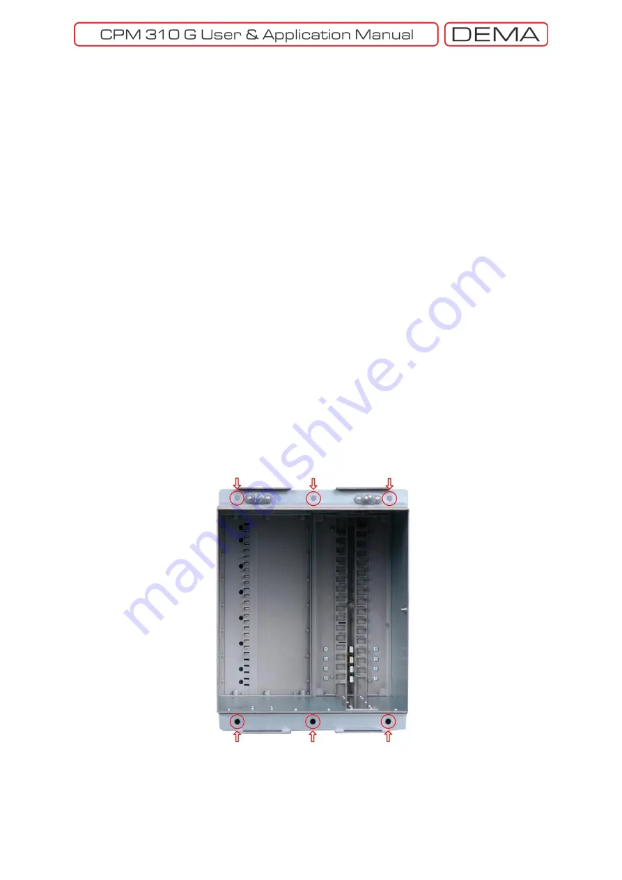
Use the supplied 5 sets of M4 custom screws, standard M4 nuts and washers to fix the case onto
the panel. Drive the screws from the front first, and then tighten the nuts on the washers from
the backside of the panel.
Make sure that the supplied custom screws are used for mounting. Using any other
screws may result in sealing failure and loss of protection degree of the cover!
Make sure that all 5 mounting holes are screwed and tightened. Mounting the case from
lesser points may result in mechanical stresses and bending on the case construction due
to any possible deformations on the panel. Such inappropriate applications may harden
driving the internal unit into or out of the case.
4.
Always use torque drivers when working with the relay. Apply (0.69 – 0.82) N·m torque when
tightening the nuts.
MOUNTING THE INNER UNIT AND THE COVER
1.
Rotate the lock handle to provide an approximate degree of 90 between the handle and the
internal unit. Drive the internal unit into the case until the unit fits well, the press the lock button
to lock the unit in place. This will ensure healthy electrical connection between the internal unit
and the case.
2.
Place the bottom part of the cover into its place on the case first, and then close the cover on the
case. Make sure the cover fits in its place and the sealing is provided between the cover and the
case. Tighten the mounting element on the cover.
0.20 N·m torque is sufficient to provide IP52 protection when tightening the mounting
elements on the cover. Never apply torque values higher than 0.29 N·m! This may
damage the mounting elements and may lead the cover out of service! □
Mounting Holes
Содержание CPM 310 G
Страница 1: ...CPM 310 G Digital Overcurrent Protection Relay User Application Manual vEN 2016 03...
Страница 2: ...2...
Страница 6: ...6 ABOUT DEMA...
Страница 11: ...11 INTRODUCTION...
Страница 32: ...32 PACKING LABELING INFORMATION...
Страница 34: ...34 OPERATING MANUAL...
Страница 53: ...53 RELAY MENUS MANUAL...
Страница 55: ...55 The Menu Tree...
Страница 56: ...56...
Страница 57: ...57...
Страница 58: ...58...
Страница 59: ...59...
Страница 60: ...60...
Страница 61: ...61...
Страница 128: ...128 DIGICONNECT PC PROGRAM MANUAL...
Страница 189: ...189 APPLICATION DIAGRAMS...
Страница 191: ...191 Sample Power Transformer Protection Application Diagram...
Страница 193: ...193 FUNDAMENTAL CABLING DIAGRAM...
Страница 195: ...195 APPLICATION DIAGRAM NO 2 Function Function Activation Address Output Settings Internal Error Alarm Automatic...
Страница 203: ...203 APPLICATION DIAGRAM NO 10 RS485 Cabling...
Страница 204: ...204 TECHNICAL DATA...
Страница 220: ...220 GLOSSARY...


