


- 167 -
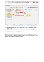
Settings
» Automatic Control Settings » Auto
-recloser Settings
»
Settings Group 1/2
A.
Once the group selection is made on the menu appeared by clicking
Auto-reclose Settings
button under the
Automatic Control Settings
window,
Auto-reclose Settings
main menu comes up.
B.
Save to Buffer
button sends the parameter changes to the DigiConnect buffer. When changes are to be applied
to CPM 310 G unit,
Save to Device
button must be utilized, which is located under the
Buffer
tab.
1.
This area comprises functionality and characteristics monitoring and modifying fields for the AR function.
Auto-reclose
parameter is to be set
Active
or
Passive
to have the function into or out of service.
tD1-tD4
parameters are to be set within the range of (0.01-300) s by 0.01s stepping to determine the dead
time durations between the auto-reclosing cycles.
tReset
parameter is set within the range of (0.2-600) s in steps of 0.01s to determine when the auto-
recloser decides that the network has reached to the normal service conditions after the last successful
shot.
tInhibit
parameter is set within the range of (0.2-600) s in steps of 0.01s to determine how long to prohibit
triggering of an auto-reclose session after the circuit breaker is closed manually.
Cycle Limits
parameters can be set between 1 and 4 to determine the limits of maximum cycles.
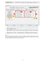
2.
This area shows the active settings of auto-reclosing algorithm. The algorithm can be modified via the controls in
area 3, as marked on the picture above. See the paragraph below.
3.
There are two groups of control check boxes in this area.
The first group titled
Reclose
allows the user to decide on which cycles and for which functions an auto-
reclosing shot is to be triggered. Note that each box in the matrix is aligned to a protection function on the
abscissa and an AR cycle number on the ordinate. The sample settings on the picture above provide 4 cycles
of auto-reclosing if tI>> or tI
e
>> protection functions trigger a trip.
The second group titled
Trip
allows the user to decide on which cycles and for which functions tripping is
allowed. Note that there is an extra column of locked check boxes with
S
title, which shows that the
initiating trips by protection functions are allowed by default. Prohibition of initial tripping of protection
functions are not allowed here.
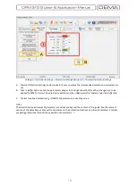
7
The sample settings on the picture above allow tripping by any active
protection functions at all 4 cycles
Looking at the picture above, it can be concluded that these sample settings allow tripping for any protection
functions at any cycles, however, if tripping is triggered by a function other than tI>> or tI
e
>> on any of the
cycles, the auto-reclose session will be stopped and the auto-recloser will be blocked.
□
7
If anyway tripping by certain active protective functions are needed to be prohibited, utilize the
Trip Settings menu under the
Automatic Control Settings menu.
Содержание CPM 310 G
Страница 1: ...CPM 310 G Digital Overcurrent Protection Relay User Application Manual vEN 2016 03...
Страница 2: ...2...
Страница 6: ...6 ABOUT DEMA...
Страница 11: ...11 INTRODUCTION...
Страница 32: ...32 PACKING LABELING INFORMATION...
Страница 34: ...34 OPERATING MANUAL...
Страница 53: ...53 RELAY MENUS MANUAL...
Страница 55: ...55 The Menu Tree...
Страница 56: ...56...
Страница 57: ...57...
Страница 58: ...58...
Страница 59: ...59...
Страница 60: ...60...
Страница 61: ...61...
Страница 128: ...128 DIGICONNECT PC PROGRAM MANUAL...
Страница 189: ...189 APPLICATION DIAGRAMS...
Страница 191: ...191 Sample Power Transformer Protection Application Diagram...
Страница 193: ...193 FUNDAMENTAL CABLING DIAGRAM...
Страница 195: ...195 APPLICATION DIAGRAM NO 2 Function Function Activation Address Output Settings Internal Error Alarm Automatic...
Страница 203: ...203 APPLICATION DIAGRAM NO 10 RS485 Cabling...
Страница 204: ...204 TECHNICAL DATA...
Страница 220: ...220 GLOSSARY...


