


- 135 -
Device Manager Dialogue
Protocol:
CPM 310 G relays can communicate using
MODBUS, IEC60870-5-103 and DEMCOM protocols.
When communicating with CPM 310 G via a PC,
following points must be considered.
o
When communication is to be established via
the USB port located on the front face of CPM
310 G; MODBUS or DEMCOM protocol may be
selected.
o
When communication is to be established via
the RS485 serial port located on the backside
terminals of CPM 310 G; MODBUS, IEC60870-5-
103 or DEMCOM protocol may be selected.
Baud rate:
Baud rate (communications speed) may be
set to 1,200, 2,400, 4,800, 9,600, 19,200 or 38,400
bauds. On SCADA applications, communications speed
may vary by the hardware and software used and any of
the listed speed options may be required. When direct
communication to CPM 310 G via a PC is intended,
setting the baud rate to 38,400 will be most favorable.
Remark
When direct communication to CPM 310 G via a PC is
intended, the communications settings of CPM 310 G must
be analogous to the settings shown on
Startup Dialogue 4
.
For detailed information on these settings, please refer to
Communications Settings Menu
section of
Relay Menus
Manual
.
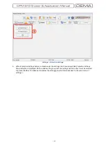
4.
Once the settings are completed, click the
OK
button
Connection Settings
menu (Startup Dialogue 4)
to establish the connection. At this point, the password screen is monitored, as shown in the picture
Startup Dialogue 5
below. If the password is entered correctly and
OK
button is hit, the DigiConnect
program will be started successfully.
□
Startup Dialogue 5
Содержание CPM 310 G
Страница 1: ...CPM 310 G Digital Overcurrent Protection Relay User Application Manual vEN 2016 03...
Страница 2: ...2...
Страница 6: ...6 ABOUT DEMA...
Страница 11: ...11 INTRODUCTION...
Страница 32: ...32 PACKING LABELING INFORMATION...
Страница 34: ...34 OPERATING MANUAL...
Страница 53: ...53 RELAY MENUS MANUAL...
Страница 55: ...55 The Menu Tree...
Страница 56: ...56...
Страница 57: ...57...
Страница 58: ...58...
Страница 59: ...59...
Страница 60: ...60...
Страница 61: ...61...
Страница 128: ...128 DIGICONNECT PC PROGRAM MANUAL...
Страница 189: ...189 APPLICATION DIAGRAMS...
Страница 191: ...191 Sample Power Transformer Protection Application Diagram...
Страница 193: ...193 FUNDAMENTAL CABLING DIAGRAM...
Страница 195: ...195 APPLICATION DIAGRAM NO 2 Function Function Activation Address Output Settings Internal Error Alarm Automatic...
Страница 203: ...203 APPLICATION DIAGRAM NO 10 RS485 Cabling...
Страница 204: ...204 TECHNICAL DATA...
Страница 220: ...220 GLOSSARY...


