


- 114 -
Delaying Logic Selectivity Settings Menu
Delaying Logic Selectivity Settings Menu
(Displayed
briefly as
Delaying Settings
on the relay menus) is a
control menu that enables the users to utilize the
Delaying Logic Selectivity
scheme on a number of
relays that are protecting the same circuit, and are
installed back-to-back. Applying the
Delaying Logic
Selectivity
scheme on systems eliminates the need for
time grading selectivity schemes, which, by their
nature, prolong the clearance times of faults and can
be applied with relatively small number of steps of
selectivity.
Delaying Logic Selectivity
function operates with principles
similar to those of
Blocking Logic Selectivity
. When a fault
current flows through the current transformers of two or
more relays which are located in series regarding to the
primary circuit, the upstream relay tripping is delayed by the
downstream relay by means of a dedicated input. That is
achieved utilizing a pilot line, which conducts an AC or DC
signal from the downstream relay to the input of the
upstream relay. Regardless of the number of the relays on
the system that sense the fault, the tripping of each relay is
delayed by the nearest downstream relay instantly and
independently; that results the tripping of the only relay of
whose tripping is not delayed – which is naturally the nearest
relay to the fault location. Note that the tripping of the relay
that is nearest to the fault location is not delayed, for that the
next downstream relay reads no current.
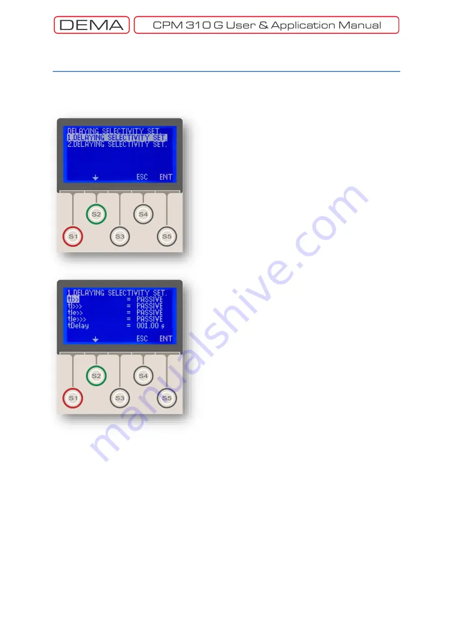
When the
Delaying Logic Selectivity Settings Menu
is
entered (top picture), the user is asked to select the
settings group. Once the selection is made by the
S5
button (
ENT
), the submenu shown on the bottom
pictures appear.
On the submenu, it is decided whether the protection
function tripping times are to be translated or not when
CPM 310 G unit receives a delaying signal, as described
recently. The sample picture on the bottom of the
previous page shows the default settings, which will
not allow any delaying actions to be trigger by inputs.
If any of the protection functions (e.g. tI>>) are
needed to be delayed by an input signal, the parameter
of that function must be set as
Active
.
It must be kept in mind that the setting the parameters
on the Delaying Logic Selectivity Settings Menu is not
enough to utilize the delaying logic selectivity system;
additional settings and applications must be done for
commissioning, which are:
Programming of the input and output relays,
Pilot wiring between the relays. □
Main Screen » Menu »
Automatic Control Settings »
Delaying Logic Sel. Settings
Содержание CPM 310 G
Страница 1: ...CPM 310 G Digital Overcurrent Protection Relay User Application Manual vEN 2016 03...
Страница 2: ...2...
Страница 6: ...6 ABOUT DEMA...
Страница 11: ...11 INTRODUCTION...
Страница 32: ...32 PACKING LABELING INFORMATION...
Страница 34: ...34 OPERATING MANUAL...
Страница 53: ...53 RELAY MENUS MANUAL...
Страница 55: ...55 The Menu Tree...
Страница 56: ...56...
Страница 57: ...57...
Страница 58: ...58...
Страница 59: ...59...
Страница 60: ...60...
Страница 61: ...61...
Страница 128: ...128 DIGICONNECT PC PROGRAM MANUAL...
Страница 189: ...189 APPLICATION DIAGRAMS...
Страница 191: ...191 Sample Power Transformer Protection Application Diagram...
Страница 193: ...193 FUNDAMENTAL CABLING DIAGRAM...
Страница 195: ...195 APPLICATION DIAGRAM NO 2 Function Function Activation Address Output Settings Internal Error Alarm Automatic...
Страница 203: ...203 APPLICATION DIAGRAM NO 10 RS485 Cabling...
Страница 204: ...204 TECHNICAL DATA...
Страница 220: ...220 GLOSSARY...


