


Geo Brick Drive User Manual
Motor Setup
185
Absolute Power-On Phasing: HiperFace
With HiperFace, the absolute serial data can be used to establish a phase reference position on power-up
without moving the motor. A custom PLC is suggested for reading the absolute power-on position
directly from the raw serial HiperFace data registers.
Note
Prior to implementing a power-on phasing routine, the user should
verify that the motor can be phased manually, be able to execute open-
loop moves successfully (output and encoder direction matching), and
possibly perform jog commands (requires PID tuning).
A one-time simple test (per installation) is performed, preferably on an unloaded motor, to find the motor
phase position offset:
1.
Execute the power-position read PLC to ensure that the actual position is correct and up to date
2.
Record the values of Ixx29, and Ixx79 to restore them at the end of test (if applicable)
3.
Set Ixx29=0, and write a positive value to Ixx79 then issue a #nO0 (where n is the motor
number). 500 is a conservative value for Ixx79 to start with. Adjust appropriately (most likely to
increase) to force the motor to lock tightly onto a phase
4.
Wait for the motor to settle
5.
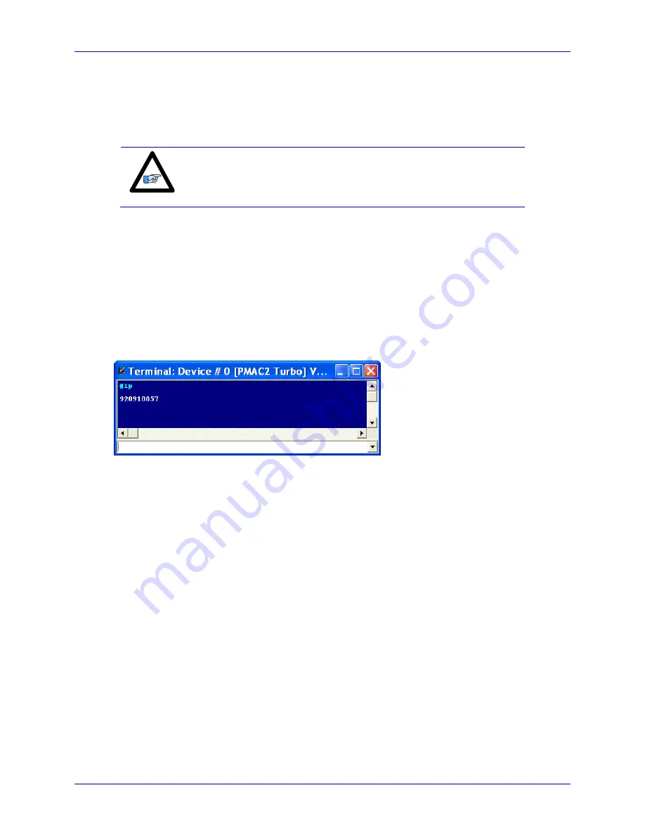
Record the absolute position from the position window or issue a #nP to return the motor
position in the terminal window
6.
Issue a #nK to kill the motor
7.
Restore Ixx29, and Ixx79 to their original values (if applicable)
8.
Enter the recorded value in the corresponding motor/channel definition in the example plc below
The following example PLC computes and corrects for the phase position register (Mxx71) for channels 1
through 8. It is pre-configured for the user to input their encoder/motor information, also to specify which
channels are to perform an absolute power-on phasing.
Using The Absolute Power-On Phasing Example PLC
Under the User Input section:
1.
In MtrxSF, enter the motor scale factor.
For rotary encoders, this is the number of counts per revolution = 2
Single-Turn Resolution
For Linear encoders, this is the number of counts per user units (i.e. mm) = 1/Encoder Resolution
2.
In MtrxPhaseTest, enter the position value recorded in the manual phasing test described above.
3.
In ChPhaseSel, specify which channels are desired to perform an absolute power-on phasing.
This value is in hexadecimal. A value of 1 in the corresponding field specifies that this channel is
connected, 0 specifies that it is not connected and should not perform phasing. Examples:
Содержание Geo Brick
Страница 5: ...4...
Страница 286: ...Geo Brick Drive User Manual Appendix A 286 APPENDIX A Schematic Samples Watchdog X15 Inputs J6 J7...
Страница 287: ...Geo Brick Drive User Manual Appendix A 287 Outputs J6 J7 603793 109 and earlier Outputs J6 J7 603793 10A and later...
Страница 288: ...Geo Brick Drive User Manual Appendix A 288 Limits Flags J4...


