


Step 2:
Increase the value of the proportional gain until the point of instability is reached (sustained oscillations) and the critical value of gain,
K
u
, is
reached.
Step 3:
Measure the period of oscillation to obtain the critical time constant,
P
u
.
Step 4:
Use the table above to calculate the necessary PID control parameters.
3.5 General Aspects of EMC
3.5.1 General Aspects of EMC Emissions
Electrical interference is usually conducted at frequencies in the range of 150 kHz to 30 MHz. Airborne interference from the drive system in the range
30 MHz to 1 GHz is generated from the inverter, motor cable, and the motor.
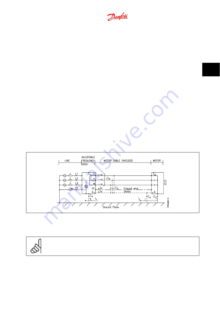
As shown in the figure below, capacitive currents in the motor cable coupled with a high dV/dt from the motor voltage generate leakage currents.
The use of a shielded motor cable increases the leakage current (see figure below), because shielded cables have higher capacitance to ground than
non-shielded cables. If the leakage current is not filtered, it will cause greater interference on the line power in the radio frequency range below approx-
imately 5 MHz. Since the leakage current (I
1
) is carried back to the unit through the shield (I
3
), there will in principle only be a small electro-magnetic
field (I
4
) from the shielded motor cable according to the below figure.
The shield reduces the radiated interference, but increases the low-frequency interference in the line power supply. The motor cable shield must be
connected to the adjustable frequency drive enclosure as well as on the motor enclosure. This is best done by using integrated shield clamps so as to
avoid twisted shield ends (pigtails). These increase the shield impedance at higher frequencies, which reduces the shield effect and increases the leakage
current (I
4
).
If a shielded cable is used for the serial communication busserial communication bus, relay, control cable, signal interface and brake, the shield must be
mounted on the enclosure at both ends. In some situations, however, it will be necessary to break the shield to avoid current loops.
If the shield is to be placed on a mounting plate for the adjustable frequency drive, the mounting plate must be made of metal, because the shield currents
have to be conveyed back to the unit. Moreover, ensure good electrical contact from the mounting plate through the mounting screws to the adjustable
frequency driver chassis.
NOTE!
When non-shielded cables are used, some emission requirements are not complied with, although the immunity requirements are
observed.
FC 300 Design Guide
3 Introduction to AutomationDrive FC 300
MG.33.BC.22 - VLT
®
is a registered Danfoss trademark
3-23
3


