


Troubleshooting by Indication on the Remote Controller
SiBE37-701
252
Troubleshooting
3. Troubleshooting by Indication on the Remote
Controller
3.1
“
A0
”
Indoor Unit:
Error of External Protection Device
Remote
Controller
Display
A0
Applicable
Models
All indoor unit models
Method of
Malfunction
Detection
Detect open or short circuit between external input terminals in indoor unit.
Malfunction
Decision
Conditions
When an open circuit occurs between external input terminals with the remote controller set to
"external ON/OFF terminal".
Supposed
Causes
Actuation of external protection device
Improper field set
Defect of indoor unit PC board
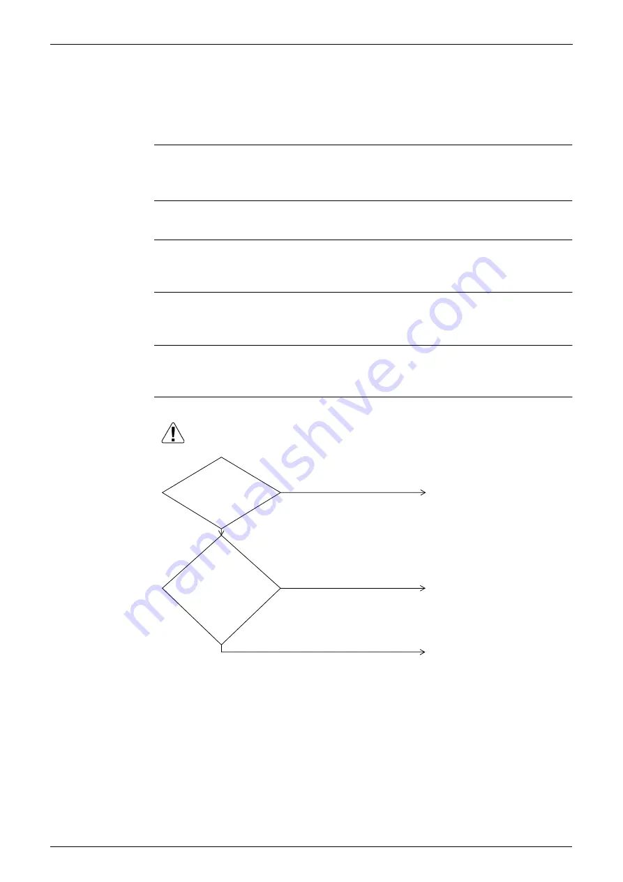
Troubleshooting
(V2776)
Caution
Be sure to turn off power switch before connect or disconnect connector,
or parts damage may be occurred.
Indoor unit PC board replacement.
Actuation of external protection
device.
Change the second code No. to
"01" or "02" .
External
protection device is
connected to terminals T1
and T2 of the indoor
unit terminal
block.
ON/OFF
input from
outside (mode No. 12,
first code No. 1) has been
set to external protection
device input (second
code No. 03)
by remote
controller.
YES
NO
NO
YES
Содержание VRV III REYQ10PY1B
Страница 1: ...REYQ8 48PY1B R 410A Heat Recovery 50Hz SiBE37 701 ...
Страница 111: ...Refrigerant Flow for Each Operation Mode SiBE37 701 100 Refrigerant Circuit ...
Страница 252: ...SiBE37 701 Troubleshooting by Remote Controller Troubleshooting 241 ...
Страница 395: ...Piping Diagrams SiBE37 701 384 Appendix 1 Piping Diagrams 1 1 Outdoor Unit REYQ8P 10P 12P 3D058154B S1NPH S2NPL ...
Страница 396: ...SiBE37 701 Piping Diagrams Appendix 385 REYQ14P 16P 3D058153B S2NPL S1NPH ...
Страница 397: ...Piping Diagrams SiBE37 701 386 Appendix REMQ8P 3D057743 ...
Страница 398: ...SiBE37 701 Piping Diagrams Appendix 387 REMQ10P 12P 3D057742 ...
Страница 399: ...Piping Diagrams SiBE37 701 388 Appendix REMQ14P 16P 3D057741 ...
Страница 400: ...SiBE37 701 Piping Diagrams Appendix 389 1 2 Indoor Unit FXFQ P ...
Страница 405: ...Piping Diagrams SiBE37 701 394 Appendix 1 3 BS Unit 4D057985A ...
Страница 414: ...SiBE37 701 Wiring Diagrams for Reference Appendix 403 2 3 Indoor Unit FXFQ20P 25P 32P 40P 50P 63P 80P 100P 125PVEB ...
Страница 415: ...Wiring Diagrams for Reference SiBE37 701 404 Appendix FXZQ20M 25M 32M 40M 50MV1 ...
Страница 416: ...SiBE37 701 Wiring Diagrams for Reference Appendix 405 FXCQ20M 25M 32M 63MV3 ...
Страница 417: ...Wiring Diagrams for Reference SiBE37 701 406 Appendix FXCQ40M 50M 80M 125MV3 ...
Страница 420: ...SiBE37 701 Wiring Diagrams for Reference Appendix 409 FXDQ20M 25MV3 ...
Страница 421: ...Wiring Diagrams for Reference SiBE37 701 410 Appendix FXSQ20M 25M 32M 40M 50M 63MV3 ...
Страница 422: ...SiBE37 701 Wiring Diagrams for Reference Appendix 411 FXSQ80M 100M 125MV3 ...
Страница 447: ...Example of connection SiBE37 701 436 Appendix ...
Страница 453: ...Method of Checking the Inverter s Power Transistors and Diode Modules SiBE37 701 442 Appendix ...
Страница 467: ...SiBE37 701 iv Index ...
Страница 471: ...SiBE37 701 viii Drawings Flow Charts ...


