


SiBE37-701
Field Setting
Test Operation
189
3.
Field Setting
3.1
Field Setting from Remote Controller
Individual function of indoor unit can be changed from the remote controller. At the time of
installation or after service inspection / repair, make the local setting in accordance with the
following description.
Wrong setting may cause malfunction.
(When optional accessory is mounted on the indoor unit, setting for the indoor unit may be
required to change. Refer to information in the option handbook.)
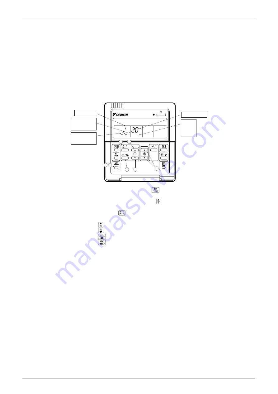
3.1.1 Wired Remote Controller <BRC1C61, 62>
1. When in the normal mode, press the “
” button for a minimum of four seconds, and the
FIELD SET MODE is entered.
2. Select the desired MODE NO. with the “
” button (
).
3. During group control, when setting by each indoor unit (mode No. 20, 22 and 23 have been
selected), push the “
” button (
) and select the INDOOR UNIT NO to be set. (This
operation is unnecessary when setting by group.)
4. Push the “
” upper button (
) and select FIRST CODE NO.
5. Push the “
” lower button (
) and select the SECOND CODE NO.
6. Push the “
” button (
) once and the present settings are SET.
7. Push the “
” button (
) to return to the NORMAL MODE.
(Example)
If during group setting and the time to clean air filter is set to FILTER CONTAMINATION,
HEAVY, SET MODE NO. to “10” FIRST CODE NO. to “0”, and SECOND CODE NO. to “02”.
SETTING
TEST
UNIT NO.
3
4
5
6
7
1
2
FIELD
SET
MODE
UNIT NO.
.
SECOND
CODE NO.
.
MODE NO.
FIRST
CODE NO.
.
(V0292)
Содержание VRV III REYQ10PY1B
Страница 1: ...REYQ8 48PY1B R 410A Heat Recovery 50Hz SiBE37 701 ...
Страница 111: ...Refrigerant Flow for Each Operation Mode SiBE37 701 100 Refrigerant Circuit ...
Страница 252: ...SiBE37 701 Troubleshooting by Remote Controller Troubleshooting 241 ...
Страница 395: ...Piping Diagrams SiBE37 701 384 Appendix 1 Piping Diagrams 1 1 Outdoor Unit REYQ8P 10P 12P 3D058154B S1NPH S2NPL ...
Страница 396: ...SiBE37 701 Piping Diagrams Appendix 385 REYQ14P 16P 3D058153B S2NPL S1NPH ...
Страница 397: ...Piping Diagrams SiBE37 701 386 Appendix REMQ8P 3D057743 ...
Страница 398: ...SiBE37 701 Piping Diagrams Appendix 387 REMQ10P 12P 3D057742 ...
Страница 399: ...Piping Diagrams SiBE37 701 388 Appendix REMQ14P 16P 3D057741 ...
Страница 400: ...SiBE37 701 Piping Diagrams Appendix 389 1 2 Indoor Unit FXFQ P ...
Страница 405: ...Piping Diagrams SiBE37 701 394 Appendix 1 3 BS Unit 4D057985A ...
Страница 414: ...SiBE37 701 Wiring Diagrams for Reference Appendix 403 2 3 Indoor Unit FXFQ20P 25P 32P 40P 50P 63P 80P 100P 125PVEB ...
Страница 415: ...Wiring Diagrams for Reference SiBE37 701 404 Appendix FXZQ20M 25M 32M 40M 50MV1 ...
Страница 416: ...SiBE37 701 Wiring Diagrams for Reference Appendix 405 FXCQ20M 25M 32M 63MV3 ...
Страница 417: ...Wiring Diagrams for Reference SiBE37 701 406 Appendix FXCQ40M 50M 80M 125MV3 ...
Страница 420: ...SiBE37 701 Wiring Diagrams for Reference Appendix 409 FXDQ20M 25MV3 ...
Страница 421: ...Wiring Diagrams for Reference SiBE37 701 410 Appendix FXSQ20M 25M 32M 40M 50M 63MV3 ...
Страница 422: ...SiBE37 701 Wiring Diagrams for Reference Appendix 411 FXSQ80M 100M 125MV3 ...
Страница 447: ...Example of connection SiBE37 701 436 Appendix ...
Страница 453: ...Method of Checking the Inverter s Power Transistors and Diode Modules SiBE37 701 442 Appendix ...
Страница 467: ...SiBE37 701 iv Index ...
Страница 471: ...SiBE37 701 viii Drawings Flow Charts ...


