SiBE37-701
Troubleshooting (OP: Unified ON/OFF Controller)
Troubleshooting
377
[Check 10] Check for causes of wet operation.
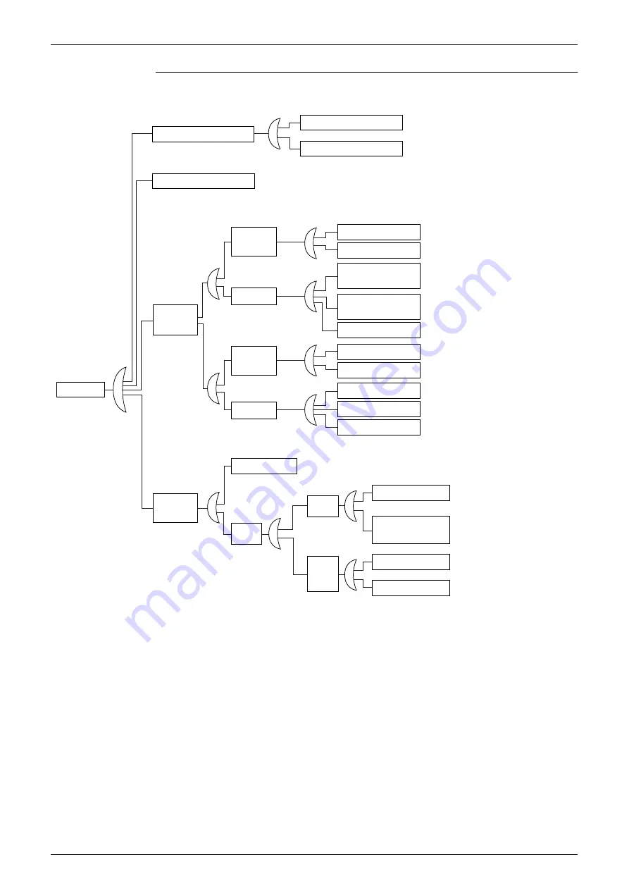
Referring to the Fault Tree Analysis (FTA) shown below, identify faulty points.
Refrigerant accumulation
Overcharge of refrigerant
Faulty crankcase heater
Frequent ON/OFF of compressor
[Cooling]
Indoor unit
motorized valve
opens too
much. (*1)
[Heating]
Outdoor unit
motorized valve
opens too
much. (*2)
Faulty control
of superheated
degree
Faulty indoor
unit motorized
valve
Faulty outdoor
unit motorized
valve
Faulty control
Faulty control
Faulty valve coil
Faulty control PC board
Faulty valve body
Faulty valve coil
Faulty valve body
Faulty power pressure sensor
Faulty suction pipe thermistor
Faulty control PC board
Faulty indoor unit
gas pipe thermistor
Faulty indoor unit
liquid pipe thermistor
←
Refer to information in the [Check 6]
section.
←
Does the valve coil have normal
resistance and insulation?
(Refer to information in the [Check 11]
section.)
←
Is the connector correctly connected?
Are the thermistor resistance
characteristics normal?
←
Is the connector correctly connected?
Are the thermistor resistance
characteristics normal?
←
Does the valve coil have normal
resistance and insulation?
(Refer to information in the [Check 11]
section.)
←
Are the voltage characteristics normal?
←
Is the connector correctly connected?
Does the thermistor have normal
resistance characteristics?
←
Is the pressure reading of the service
checker corresponding to the actual
measurement of the sensor?
←
Can the fan motor be rotated by
hand?
Does the fan motor coil have
normal resistance and
insulation?
←
Does the air filter get clogged?
←
Are there any obstacles in the air
passage?
Wet operation
Degraded
evaporation
capacity
Increased
resistance
in air
passage
Dirty evaporator
Reduced
air quantity
Reduced
fan output
*1: "Superheated degree control" in cooling operation is exercised with the indoor unit motorized valve. (Refer to
*2: "Superheated degree control" in heating operation is exercised with the outdoor unit motorized valve (EV1).
(Refer to information on P114.)
*3: Guideline of superheated degree to judge as wet operation
Suction gas superheated degree: Not more than 3
°
C;
Discharge gas superheated degree: Not more than
15
°
C, except immediately after compressor starts up or is running under drooping control.
(Use the values shown above as a guideline. Even if the superheated degree falls in the range, the compressor
may be normal depending on other conditions.)
Faulty fan motor
Dirty filter
Obstacles
Faulty control PC board
(including faulty
capacity setting)
←
Does the heat exchanger get clogged?
Содержание VRV III REYQ10PY1B
Страница 1: ...REYQ8 48PY1B R 410A Heat Recovery 50Hz SiBE37 701 ...
Страница 111: ...Refrigerant Flow for Each Operation Mode SiBE37 701 100 Refrigerant Circuit ...
Страница 252: ...SiBE37 701 Troubleshooting by Remote Controller Troubleshooting 241 ...
Страница 395: ...Piping Diagrams SiBE37 701 384 Appendix 1 Piping Diagrams 1 1 Outdoor Unit REYQ8P 10P 12P 3D058154B S1NPH S2NPL ...
Страница 396: ...SiBE37 701 Piping Diagrams Appendix 385 REYQ14P 16P 3D058153B S2NPL S1NPH ...
Страница 397: ...Piping Diagrams SiBE37 701 386 Appendix REMQ8P 3D057743 ...
Страница 398: ...SiBE37 701 Piping Diagrams Appendix 387 REMQ10P 12P 3D057742 ...
Страница 399: ...Piping Diagrams SiBE37 701 388 Appendix REMQ14P 16P 3D057741 ...
Страница 400: ...SiBE37 701 Piping Diagrams Appendix 389 1 2 Indoor Unit FXFQ P ...
Страница 405: ...Piping Diagrams SiBE37 701 394 Appendix 1 3 BS Unit 4D057985A ...
Страница 414: ...SiBE37 701 Wiring Diagrams for Reference Appendix 403 2 3 Indoor Unit FXFQ20P 25P 32P 40P 50P 63P 80P 100P 125PVEB ...
Страница 415: ...Wiring Diagrams for Reference SiBE37 701 404 Appendix FXZQ20M 25M 32M 40M 50MV1 ...
Страница 416: ...SiBE37 701 Wiring Diagrams for Reference Appendix 405 FXCQ20M 25M 32M 63MV3 ...
Страница 417: ...Wiring Diagrams for Reference SiBE37 701 406 Appendix FXCQ40M 50M 80M 125MV3 ...
Страница 420: ...SiBE37 701 Wiring Diagrams for Reference Appendix 409 FXDQ20M 25MV3 ...
Страница 421: ...Wiring Diagrams for Reference SiBE37 701 410 Appendix FXSQ20M 25M 32M 40M 50M 63MV3 ...
Страница 422: ...SiBE37 701 Wiring Diagrams for Reference Appendix 411 FXSQ80M 100M 125MV3 ...
Страница 447: ...Example of connection SiBE37 701 436 Appendix ...
Страница 453: ...Method of Checking the Inverter s Power Transistors and Diode Modules SiBE37 701 442 Appendix ...
Страница 467: ...SiBE37 701 iv Index ...
Страница 471: ...SiBE37 701 viii Drawings Flow Charts ...


