


SiBE37-701
Field Setting
Test Operation
191
3.1.3 Simplified Remote Controller
BRC2A51
BRC2C51
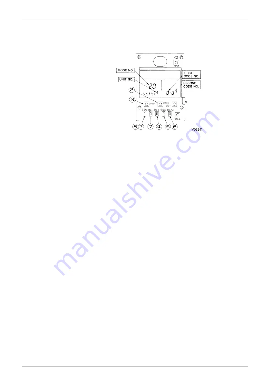
1. Remove the upper part of remote controller.
2. When in the normal mode, press the [BS6] BUTTON (
) (field set), and the FIELD SET
MODE is entered.
3. Select the desired MODE No. with the [BS2] BUTTON (
) (temperature setting
▲
) and the
[BS3] BUTTON (
) (temperature setting
▼
).
4. During group control, when setting by each indoor unit (mode No. 20, 22, and 23 have been
selected), push the [BS8] (
) BUTTON (unit No.) and select the INDOOR UNIT NO. to be
set. (This operation is unnecessary when setting by group.)
5. Push the [BS9] BUTTON (
) (set A) and select FIRST CODE NO.
6. Push the [BS10] BUTTON (
) (set B) and select SECOND CODE NO.
7. Push the [BS7] BUTTON (
) (set/cancel) once and the present settings are SET.
8. Push the [BS6] BUTTON (
) (field set) to return to the NORMAL MODE.
9. (Example) If during group setting and the time to clean air filter is set to FILTER
CONTAMINATION - HEAVY, SET MODE NO. to “10”, FIRST CODE NO. to “0”, and
SECOND CODE NO. to “02”.
Содержание VRV III REYQ10PY1B
Страница 1: ...REYQ8 48PY1B R 410A Heat Recovery 50Hz SiBE37 701 ...
Страница 111: ...Refrigerant Flow for Each Operation Mode SiBE37 701 100 Refrigerant Circuit ...
Страница 252: ...SiBE37 701 Troubleshooting by Remote Controller Troubleshooting 241 ...
Страница 395: ...Piping Diagrams SiBE37 701 384 Appendix 1 Piping Diagrams 1 1 Outdoor Unit REYQ8P 10P 12P 3D058154B S1NPH S2NPL ...
Страница 396: ...SiBE37 701 Piping Diagrams Appendix 385 REYQ14P 16P 3D058153B S2NPL S1NPH ...
Страница 397: ...Piping Diagrams SiBE37 701 386 Appendix REMQ8P 3D057743 ...
Страница 398: ...SiBE37 701 Piping Diagrams Appendix 387 REMQ10P 12P 3D057742 ...
Страница 399: ...Piping Diagrams SiBE37 701 388 Appendix REMQ14P 16P 3D057741 ...
Страница 400: ...SiBE37 701 Piping Diagrams Appendix 389 1 2 Indoor Unit FXFQ P ...
Страница 405: ...Piping Diagrams SiBE37 701 394 Appendix 1 3 BS Unit 4D057985A ...
Страница 414: ...SiBE37 701 Wiring Diagrams for Reference Appendix 403 2 3 Indoor Unit FXFQ20P 25P 32P 40P 50P 63P 80P 100P 125PVEB ...
Страница 415: ...Wiring Diagrams for Reference SiBE37 701 404 Appendix FXZQ20M 25M 32M 40M 50MV1 ...
Страница 416: ...SiBE37 701 Wiring Diagrams for Reference Appendix 405 FXCQ20M 25M 32M 63MV3 ...
Страница 417: ...Wiring Diagrams for Reference SiBE37 701 406 Appendix FXCQ40M 50M 80M 125MV3 ...
Страница 420: ...SiBE37 701 Wiring Diagrams for Reference Appendix 409 FXDQ20M 25MV3 ...
Страница 421: ...Wiring Diagrams for Reference SiBE37 701 410 Appendix FXSQ20M 25M 32M 40M 50M 63MV3 ...
Страница 422: ...SiBE37 701 Wiring Diagrams for Reference Appendix 411 FXSQ80M 100M 125MV3 ...
Страница 447: ...Example of connection SiBE37 701 436 Appendix ...
Страница 453: ...Method of Checking the Inverter s Power Transistors and Diode Modules SiBE37 701 442 Appendix ...
Страница 467: ...SiBE37 701 iv Index ...
Страница 471: ...SiBE37 701 viii Drawings Flow Charts ...


