


SiBE37-701
Test Operation
Test Operation
173
The automatic refrigerant charging has limits as described below.
At out of limit, the system can not operate the automatic refrigerant charging.
Outdoor temperature
: 0°C DB~43°C DB
Indoor temperature
: 10°C DB~32°C DB
Total indoor unit capacity
:
≥
80%
To speed up the process of charging refrigerant for large systems, it is recommended to first
manually charge a portion of the refrigerant first before performing automatic charging.
1.
Calculate how much refrigerant to be added using the formula explained in the chapter "How
to calculate the additional refrigerant to be charged" on page 156.
2.
The amount of pre-charging is 10 kg less than the calculated amount.
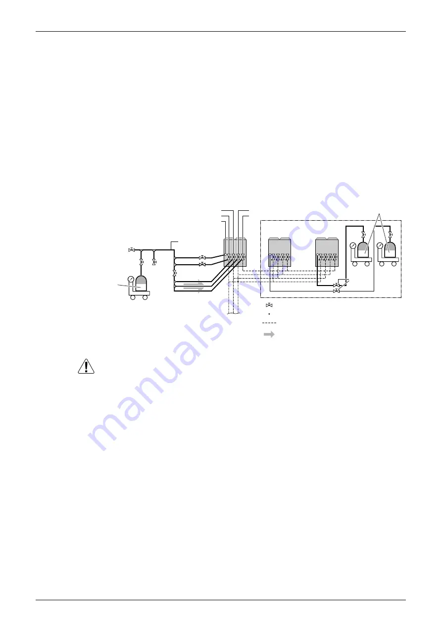
3.
Open valve B (the valves A and C, the liquid pipe, the suction gas pipe and the high
pressure/low pressure gas pipe stop valves must be left closed) and charge the refrigerant in
liquid form via the liquid pipe stop valve service port.
(See figure below)
4.
If the calculated amount of pre-charging is reached, close valve B.
At least the unit should be charged with its original amount of refrigerant (refer to the nameplate
on the unit), before starting the automatic charging.
5.
After pre-charging, perform the refrigerant charge operation as shown below and charge the
remaining refrigerant of the additional charging amount through valve A. (See above figure)
Refrigerant tank
(R410A, siphon
system)
Stop valve
Service port
Field piping
Refrigerant flow when
charging
The refrigerant will be charged with
±30 kg in 1 hour at an outdoor
temperature of 30˚C DB (12 kg at 0˚C
DB). If you need to speed up in case
of a multi system, connect the
refrigerant tank to each outdoor unit.
Measuring instrument
Suction gas pipe stop valve
High pressure/low pressure gas pipe stop valve
Valve B
Valve C
To BS-unit, indoor unit
Liquid pipe stop valve
Equalizer pipe stop valve
Valve A
Charge hose
Refrigerant charge port
Measuring
instrument
Measuring
instrument
Valve A
Refrigerant tank
(R410A, siphon
system)
Содержание VRV III REYQ10PY1B
Страница 1: ...REYQ8 48PY1B R 410A Heat Recovery 50Hz SiBE37 701 ...
Страница 111: ...Refrigerant Flow for Each Operation Mode SiBE37 701 100 Refrigerant Circuit ...
Страница 252: ...SiBE37 701 Troubleshooting by Remote Controller Troubleshooting 241 ...
Страница 395: ...Piping Diagrams SiBE37 701 384 Appendix 1 Piping Diagrams 1 1 Outdoor Unit REYQ8P 10P 12P 3D058154B S1NPH S2NPL ...
Страница 396: ...SiBE37 701 Piping Diagrams Appendix 385 REYQ14P 16P 3D058153B S2NPL S1NPH ...
Страница 397: ...Piping Diagrams SiBE37 701 386 Appendix REMQ8P 3D057743 ...
Страница 398: ...SiBE37 701 Piping Diagrams Appendix 387 REMQ10P 12P 3D057742 ...
Страница 399: ...Piping Diagrams SiBE37 701 388 Appendix REMQ14P 16P 3D057741 ...
Страница 400: ...SiBE37 701 Piping Diagrams Appendix 389 1 2 Indoor Unit FXFQ P ...
Страница 405: ...Piping Diagrams SiBE37 701 394 Appendix 1 3 BS Unit 4D057985A ...
Страница 414: ...SiBE37 701 Wiring Diagrams for Reference Appendix 403 2 3 Indoor Unit FXFQ20P 25P 32P 40P 50P 63P 80P 100P 125PVEB ...
Страница 415: ...Wiring Diagrams for Reference SiBE37 701 404 Appendix FXZQ20M 25M 32M 40M 50MV1 ...
Страница 416: ...SiBE37 701 Wiring Diagrams for Reference Appendix 405 FXCQ20M 25M 32M 63MV3 ...
Страница 417: ...Wiring Diagrams for Reference SiBE37 701 406 Appendix FXCQ40M 50M 80M 125MV3 ...
Страница 420: ...SiBE37 701 Wiring Diagrams for Reference Appendix 409 FXDQ20M 25MV3 ...
Страница 421: ...Wiring Diagrams for Reference SiBE37 701 410 Appendix FXSQ20M 25M 32M 40M 50M 63MV3 ...
Страница 422: ...SiBE37 701 Wiring Diagrams for Reference Appendix 411 FXSQ80M 100M 125MV3 ...
Страница 447: ...Example of connection SiBE37 701 436 Appendix ...
Страница 453: ...Method of Checking the Inverter s Power Transistors and Diode Modules SiBE37 701 442 Appendix ...
Страница 467: ...SiBE37 701 iv Index ...
Страница 471: ...SiBE37 701 viii Drawings Flow Charts ...


