Curtiss-Wright | PG Drives Technology
SK77981-14
136 | R-net Technical Manual | Chapter 4 – ELPM 90, JSM-LED &
SM
The programmable options are Off and 2 to 33.
If set to Off, then the relevant Axis x Up Inhibit can never be active.
If set to a numeric value, then the relevant Axis x Up Inhibit will be under the control of the Inhibit Input that
corresponds to that number.
7.8
AXIS X – UP INHIBIT IN BANDS (X = 1 TO 6)
This sets the condition of the input (assigned to Axis x Up Inhibit) that will result in an inhibit of the actuator drive in the up
direction. Up is defined as pin 2 positive with respect to pin 1 when the joystick is displaced forward. Th e inhibit can be set to
occur in any combination of bands. See Inhibits Explained in Chapter 3 Programming for more details on bands.
The programmable options are Band 0, Band 1, Band 2 and Band 3.
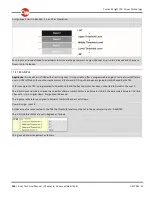
If the parameter is selected, then a drop down menu as bel ow will appear and the bands required to invoke the inhibit should
be selected. For example, if the inhibit is required for Band 3 only, then that option should be selected, as shown.
When the drop down menu is closed, a 3 will be shown in the cell.
7.9
AXIS X – DOWN ASSIGN (X = 1 TO 12)
Each actuator axis has a software inhibit for its down direction. Down is defined as pin 1 positive with respect to pin 2 when the
joystick is displaced in reverse. The inhibit can be initiated by any actual hardware inhibit in the system.
The parameter, Assign, links the software inhibit to an actual hardware inhibit. For example, if Assign: is set to 2, then the axis
can be inhibited by Inhibit Input 2.
The programmable options are Off and 2 to 33.
If set to Off, then the relevant Axis x Down Inhibit can never be active.
If set to a numeric value, then the relevant Axis x Down Inhibit will be under the control of the Inhibit Input that
corresponds to that number.
7.10
AXIS X – DOWN: INHIBIT IN BANDS (X = 1 TO 6)
This sets the condition of the input (assigned to Axis x Down Inhibit) that will result in an inhibit of the actuator drive in the
down direction. Down is defined as pin 1 positive with respect to pin 2 when the joystick is displaced backwards. The inhibit can
be set to occur in any combination of ba nds. See Inhibits Explained in Chapter 3 Programming for more details on bands.
The programmable options are Band 0, Band 1, Band 2 and Band 3.
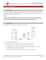
If the parameter is selected, then a drop down menu as below will appear and the bands required to invoke the in hibit should
be selected. For example, if the inhibit is required for Band 3 only, then that option should be selected, as shown.
When the drop down menu is closed, a 3 will be shown in the cell.
Содержание R-NET
Страница 1: ...PG DRIVES TECHNOLOGY R NET TECHNICAL MANUAL SK77981 14 ...
Страница 46: ...Curtiss Wright PG Drives Technology SK77981 14 46 R net Technical Manual Chapter 2 Installation 6 1 3 CRIMPING ...
Страница 58: ...Curtiss Wright PG Drives Technology SK77981 14 58 R net Technical Manual Chapter 2 Installation ...
Страница 174: ...Curtiss Wright PG Drives Technology SK77981 14 174 R net Technical Manual Chapter 8 ISM 8 ...
Страница 194: ...SK77981 14 194 R net Technical Manual Chapter 10 Diagnostics Curtiss Wright PG Drives Technology ...
Страница 206: ...SK77981 14 206 R net Technical Manual Chapter 12 Specifications Curtiss Wright PG Drives Technology ...


