Curtiss-Wright | PG Drives Technology
SK77981-14
64 | R-net Technical Manual | Chapter 3 – Programming
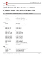
Seat Reversal
Sets the various options for wheelchairs that have a reversing seat
Charger Inhibit 3 Enable
Dedicates the Inhibit 3 input on the Power Module to operate with an On -Board Charger
Charger Inhibit 3 Latching
Sets whether the OBC inhibit (PM Inhibit 3) as described above is latching or non -latching
Charger Inhibit 1 Latching
Sets whether Inhibit 1 (JSM Charger Socket) is latching or non -latching
Charger Inhibit 1 Alarm
Sets whether an alarm sounds if there is an inhibit present on the JSM Charger Socket
Charger Inhibit 3 Alarm
Sets whether an alarm sounds if there is an inhibit present on the PM Inbibit 3
Front Wheel Drive
Front Wheel Drive Type
Sets specific specialist software to support Front Wheel D rive Wheelchairs
Front Wheel Drive
Selects specialist software for front wheel driven wheelchairs
FWD Acceleration
Sets the limit of forward acceleration when exiting a turn
Advanced Electronic Stability (AES)
Advanced Electronic Stability
Sets whether the specialist stability software is turned on
AES Rate
Sets the rate of adjustment of Advanced Electronic Stability
Motor
Global
Maximum Current Limit
Sets the long term maximum current output of the Power Module
Boost Drive Current
Sets the short term maximum current output of the Power Module
Boost Drive Time
Sets the period of time that the level of current set by Boost Drive Current is available
Current Foldback Threshold
Sets the level of current which, if exceeded, will start the current foldback timer
Current Foldback Time
Sets the period of time that the current must exceed the above parameter before the current is reduced
Current Foldback Level
Sets the level of current output reduction
Compensation
Matches the PM to the motors
Invert M1 Direction
Inverts the direction of rotation of motor channel M1 on the Power Module
Invert M2 Direction
Inverts the direction of rotation of motor channel M2 on the Power Module
Motor Swap
Swaps the motor output channels, M1 and M2, of the Power Module
*Steer Correct
Adjusts the PM outputs to compensate for mis-matched motors
*Display Speed
Sets whether the speed and odometer is displayed in miles per hour or kilometers per hour
Displays
Sets the format of the digital speed display to be Speed, Odometer or Both
Maximum Rated Speed
This calibrates the speedometer function
*Maximum Displayed Speed
This sets the operation of the graphical speed display
Joystick Stationary Time
Sets the period of time that the joystick must be deflected before drive is removed
Joystick Stationary Range
Sets the ‘window’ within which the joystick is considered to be stationary
Profiled
Compensation Factor
Allows different values of Compensation to be used across different profiles.
Inhibits
Global
Disable Inhibit 2 in Drive
Sets whether the PM Inhibit 2 input is interrogated constantly or just at entry into Drive Mode
Disable Inhibit 3 in Drive
Sets whether the PM Inhibit 3 input is interrogated constantly or just at entry into Drive Mode
Disable Inhibit 8 in Drive
For parameter information - Refer to the Specialist Chapter – ASM/TM
Disable Inhibit 9 in Drive
For parameter information - Refer to the Specialist Chapter – ASM/TM
Inputs - PM
Lower Level Threshold
Sets the threshold between Band 0 and Band 1 for a particular Inhibit Input on the PM
Middle Level Threshold
Sets the threshold between Band 1 and Band 2 for a particular Inhibit Input on the PM
Upper Level Threshold
Sets the threshold between Band 2 and Band 3 for a particular Inhibit Input on the PM
Debounce Time
Sets a debounce time for the inhibit input.
Inputs - ISM
Lower Level Threshold
Sets the threshold between Band 0 and Band 1 for a particular Inhibit Input on the ISM
Middle Level Threshold
Sets the threshold between Band 1 and Band 2 for a particular Inhibit Input on the ISM
Upper Level Threshold
Sets the threshold between Band 2 and Band 3 for a particular Inhibit Input on the ISM
Debounce Time
Sets a debounce time for the inhibit input
Inputs – ISM8/CxSM
Lower Level Threshold
For parameter information - Refer to the Chapter – ISM8
Middle Level Threshold
For parameter information - Refer to the Chapter – ISM8
Upper Level Threshold
For parameter information - Refer to the Chapter – ISM8
Debounce Time
For parameter information - Refer to the Chapter – ISM8
Содержание R-NET
Страница 1: ...PG DRIVES TECHNOLOGY R NET TECHNICAL MANUAL SK77981 14 ...
Страница 46: ...Curtiss Wright PG Drives Technology SK77981 14 46 R net Technical Manual Chapter 2 Installation 6 1 3 CRIMPING ...
Страница 58: ...Curtiss Wright PG Drives Technology SK77981 14 58 R net Technical Manual Chapter 2 Installation ...
Страница 174: ...Curtiss Wright PG Drives Technology SK77981 14 174 R net Technical Manual Chapter 8 ISM 8 ...
Страница 194: ...SK77981 14 194 R net Technical Manual Chapter 10 Diagnostics Curtiss Wright PG Drives Technology ...
Страница 206: ...SK77981 14 206 R net Technical Manual Chapter 12 Specifications Curtiss Wright PG Drives Technology ...


