Curtiss-Wright | PG Drives Technology
SK77981-14
124 | R-net Technical Manual | Chapter 4 – ELPM 90, JSM-LED &
SM
2.1.2.1 MAXIMUM SPEED INDICATOR
This is a gauge that shows the maximum speed setting of the wheelchair. There are five speed settings – step 1 is the lowest
speed and step 5 is the highest speed. For details of how to change the maximum speed setting, see sections 2.1.3 and 2.1.4.
2.1.2.2 PROFILE INDICATOR
This is an indicator that shows the selected drive profile. There may be up to 5 drive profiles available, this depends on the
programming of the control system. For details of how to select drive profiles, see sections 2.1.3 and 2.1.4.
NOTE:
A Control System utilizing an LED JSM should only be programmed with a maximum of 5 Profiles enabled.
2.1.3 SPEED / PROFILE DECREASE BUTTON
This button decreases the maximum speed setting or, if the control system is programmed for drive profile operatio n, selects a
lower drive profile.
It is possible to program the control system so this button has no effect while the wheelchair is being driven.
Refer to Chapter 3 - Programming for details.
2.1.4 SPEED / PROFILE INCREASE BUTTON
This button increases the maximum speed setting or, if the control system is programmed for drive profile operation, selects a
higher drive profile.
It is possible to program the control system so this button has no effect while the wheelchair is being driven.
Refer to Chapter 3 - Programming for details.
2.1.5 MODE BUTTON
The Mode button allows the user to navigate through the available operating Modes for the control system. The available
modes are dependent on programming and the range of auxiliary output devices connected to the control system.
Refer to Chapter 3 - Programming for details.
NOTE:
When in any Mode other than Drive and Seating the Speed and Actuator LEDs are all extinguished.
2.2
ACTUATOR INDICATOR
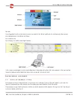
This LED set displays which Actuator channel is currently being controlled when the Control System is in Actua tor Mode. The
actuators can be programmed to work in multiple ways, refer to Chapter 3 Programming for details.
Actuator selection and operation is achieved using the Joystick.
Motions to the Left or Right select different actuator channels.
Motions Forward and Backwards move the actuator(s) selected.
Содержание R-NET
Страница 1: ...PG DRIVES TECHNOLOGY R NET TECHNICAL MANUAL SK77981 14 ...
Страница 46: ...Curtiss Wright PG Drives Technology SK77981 14 46 R net Technical Manual Chapter 2 Installation 6 1 3 CRIMPING ...
Страница 58: ...Curtiss Wright PG Drives Technology SK77981 14 58 R net Technical Manual Chapter 2 Installation ...
Страница 174: ...Curtiss Wright PG Drives Technology SK77981 14 174 R net Technical Manual Chapter 8 ISM 8 ...
Страница 194: ...SK77981 14 194 R net Technical Manual Chapter 10 Diagnostics Curtiss Wright PG Drives Technology ...
Страница 206: ...SK77981 14 206 R net Technical Manual Chapter 12 Specifications Curtiss Wright PG Drives Technology ...


