Curtiss-Wright | PG Drives Technology
SK77981-14
160 | R-net Technical Manual | Chapter 8 – ISM-8
The Inhibit connections are accommodated in 8 4-way connectors with each connector also containing 5V and 0V supply
connections for active sensors. The maximum current output the ISM-8 can supply from its voltage source is 300mA, spread in
any combination across the 8 pins.
4.3
ACTUATORS
Each actuator channel is rated at 15A maximum, although only 12A is available when the channel is programmed to 100%
speed. If currents of greater than 12A are required, the programmed speeds for that channel must be reduced. The level of
reduction is dependent upon the electrical characteristics of the actuator motor, so an empirical process to establish the level
of the reduction is required.
If the wheelchair is fitted with solid mechanical end-stops at the end of the actuator travel, it is not necessary to fit limit
switches as the ISM-8 can detect when the actuator motor has stopped and will cut off the power to it.
5
PROGRAMMING
5.1
PARAMETERS
The ISM-8 parameters are held within the programming groups of Seating and Inhibits. Within the two groups there are
individual branches called ISM-8/CxSM which hold all of the relevant parameters.
Seating/
Global
Actuator End Stop Bleep Sets whether a bleep occurs when an actuator channel is automatically end -stopped
Actuator Mode Entry Axis Sets the default axis when Seating Mode is entered
Axes Setup
Axis Channels
Sets which actuator motor channels on the ISM will operate for a particular axis
Axis Display
Sets the user display for a particular axis
Invert Channel Direction
Inverts the direction of a Channel within an Axis
Channels
Acceleration
Sets the acceleration for each actuator channel
Deceleration
Sets the deceleration for each actuator channel
Up Speed
Sets the speed in the up direction for each actuator channel
Down Speed
Sets the speed in the down direction for each actuator channel
Up Current Limit
Sets the maximum current output in the up direction for each actuator channel
Down Current Limit
Sets the maximum current output in the down direction for each actuator channel
Endstop Autodetect
Sets if the automatic endstop function for a particular actuator channel operates
Actuator Endstop Timeout
Sets the period of time before the drive is cut at an endstop position
Inputs
Inputs - ISM-8
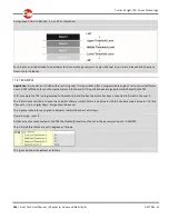
Lower Level Threshold
Sets the threshold between Band 0 and Band 1 for a particular Inhibit Input on the ISM
Middle Level Threshold
Sets the threshold between Band 1 and Band 2 for a particular Inhibit Input on the ISM
Upper Level Threshold
Sets the threshold between Band 2 and Band 3 for a particular Inhibit Input on the ISM
Debounce Time
Sets a debounce time for the inhibit input
Inhibit Type
Sets the Inhibit input to accept a signal from either an active or passive sensor.
Actuator Inhibits Channel ‘x’
Up: Assign
Links the software inhibits to an actual hardware inhibit
Up: Inhibit in Bands
Sets the condition of the input that will result in an inhibit of an actuator channel in the up direction
Up: Alarm
Sets whether an audible alarm will sound when an actuator channel is inhibited in the up direction
Up: Inhibit Active in Axis
Sets the Axes in which the Inhibit is active
Down: Assign
Links the software inhibits to an actual hardware inhibit
Содержание R-NET
Страница 1: ...PG DRIVES TECHNOLOGY R NET TECHNICAL MANUAL SK77981 14 ...
Страница 46: ...Curtiss Wright PG Drives Technology SK77981 14 46 R net Technical Manual Chapter 2 Installation 6 1 3 CRIMPING ...
Страница 58: ...Curtiss Wright PG Drives Technology SK77981 14 58 R net Technical Manual Chapter 2 Installation ...
Страница 174: ...Curtiss Wright PG Drives Technology SK77981 14 174 R net Technical Manual Chapter 8 ISM 8 ...
Страница 194: ...SK77981 14 194 R net Technical Manual Chapter 10 Diagnostics Curtiss Wright PG Drives Technology ...
Страница 206: ...SK77981 14 206 R net Technical Manual Chapter 12 Specifications Curtiss Wright PG Drives Technology ...


