39
VI. Water Piping and Trim
C. Standard Installation Requirements (continued)
C. Standard Installation Requirements
Observe the following guidelines when making the
actual installation of the boiler piping:
1. Safety Relief Valve (Required)
- The relief
valve is packaged loose with boiler and must be
installed in the location shown in Figure 20 “Factory
Supplied Piping and Trim Installation”. The relief
valve must be installed with spindle in vertical
position. Installation of the relief valve must comply
with ASME Boiler and Pressure Vessel Code,
Section IV. The standard factory shipped relief valve
is rated for 30 PSI maximum working pressure for
PHNTM210 and PHNTM285. Optional 50 PSI,
80 PSI and 100 PSI maximum working pressure
rated relief valves are available. If the valve is to be
replaced, the replacement valve must have a relief
capacity equal or exceeding the minimum relief
valve capacity shown on the ASME plate. Pipe the
relief valve discharge to a location where hot water
or steam will not create hazard or property damage
3. Phantom boiler models are factory supplied
with circulators,
which were sized for near-
boiler piping equivalent length of 50 ft. and listed
temperature differential. See Table 13 for details.
It is the installer’s responsibility to insure a proper
installation and where applicable, proper circulator
speed setting for the boiler circulator to achieve
a required flow rate. Where near-boiler piping
exceeds 50 equivalent feet, alternate circulator
selection may be required.
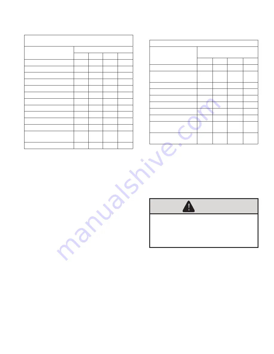
Table 14: Fitting and Valve Equivalent Length
Copper Fitting and Sweat Valve
Equivalent Length (Ft)
Fitting or Valve
Description
Copper Pipe or Valve Size
1
1¼
1½
2
90° Elbow
2.5
3.0
4.0
5.5
45° Elbow
1.0
1.2
1.5
2.0
Tee (through flow)
0.5
0.6
0.8
1.0
Tee (Branch flow)
4.5
5.5
7.0
9.0
Diverter Tee (typical)
23.5
25.0
23.0
23.0
Gate Valve
0.3
0.4
0.5
0.7
Globe Valve
25.0
36.0
46.0
56.0
Angle Valve
5.3
7.8
9.4
12.5
Ball Valve (standard port)
4.3
7.0
6.6
14.0
Ball Valve (full port)
1.9
1.4
2.2
1.3
Swing Check Valve
4.5
5.5
6.5
9.0
Flow-Check Valve
(typical)
54.0
74.0
57.0
177.0
Butterfly Valve
2.7
2.0
2.7
4.5
Threaded Fitting and Valve Equivalent Length (Ft)
Fitting or Valve
Description
Black Threaded Pipe or
Valve Size
1
1¼
1½
2
90° Elbow
2.6
3.5
4.0
5.2
Long Radius
Elbow (45° or 90°)
1.4
1.8
2.2
2.8
Tee (through flow)
1.8
2.3
2.7
3.5
Tee (Branch flow)
5.3
6.9
8.1
10.0
Close Return Bend
4.4
5.8
6.7
8.6
Gate Valve (full open)
0.7
0.9
1.1
1.4
Globe Valve (full open)
30.0
39.0
46.0
59.0
Angle Valve (full open)
13.0
17.0
20.0
26.0
Swing Check Valve
(full open)
8.7
12.0
13.0
17.0
Flow-Check Valve
(typical)
42.0
60.0
63.0
83.0
Table 14: Fitting and Valve Equivalent Length
(cont’d)
NOTE:
Table 14 is provided as reference to assist in piping design and specifies equivalent length of typical piping fittings and
valves.
if the valve opens. The end of the discharge pipe
must terminate in an unthreaded pipe. If the relief
valve is not piped to a drain, it must terminate at
least 6” above the floor. Do not run relief valve
discharge piping through an area prone to freezing.
The termination of discharge piping must be in an
area where it will not become plugged by debris.
CAUTION
Burn Hazard. Safety relief valve discharge
piping must be piped such that the potential of
severe burns is eliminated. DO NOT pipe in any
area where freezing could occur. DO NOT install
any shut-off valves, plugs or caps. Consult local
codes for proper discharge piping arrangement.
2 Circulator (Required)
– Usually at least two
circulators will be required to properly install a
Phantom Series boiler. See Paragraph B above for
information on sizing the circulators.
3. Expansion Tank (Required)
– If this boiler is
replacing an existing boiler with no other changes
in the system, the old expansion tank can generally
be reused. If the expansion tank must be replaced,
consult the expansion tank manufacturer’s literature
for proper sizing.
4. Fill Valve (Required)
– Either manual
(recommended) or automatic fill valve may be used.
However, if automatic refill is employed, a water
meter must be added to evaluate the makeup water
Содержание Phantom-X PHNTM210
Страница 7: ...7 Figure 1B Model PHNTM285 I Product Description Specifications and Dimensional Data continued...
Страница 52: ...52 VIII Electrical continued...
Страница 53: ...53 VIII Electrical continued Figure 26 Wiring Connections Diagram...
Страница 54: ...54 VIII Electrical continued Figure 27 Ladder Diagram...
Страница 59: ...59 Figure 29B Boiler to Boiler Communication with Crown Zone Panel PN 3501505 VIII Electrical continued...
Страница 109: ...109 XIII Repair Parts 1L 1K 1J 1E 1C 1D 1B 1L 1J 1A 1M 1F 1C 1D 1B 1L 1J 1A 1M 1F 1K 1G 1G 1K 1H 1G...
Страница 118: ...118...
Страница 119: ...119...


