background image

1-22

     Workstation Features

Writer: Your Name    Saved by: Lydia Sanchez    Saved date: 07/30/99 12:28 PM

Pages: 27    Words: 2779    Template: c:\word7\templates\comm.dot

File Name d-ch1.doc    Part Number 158415-001

Minitower Internal
Components
(Intel BX Chipset)

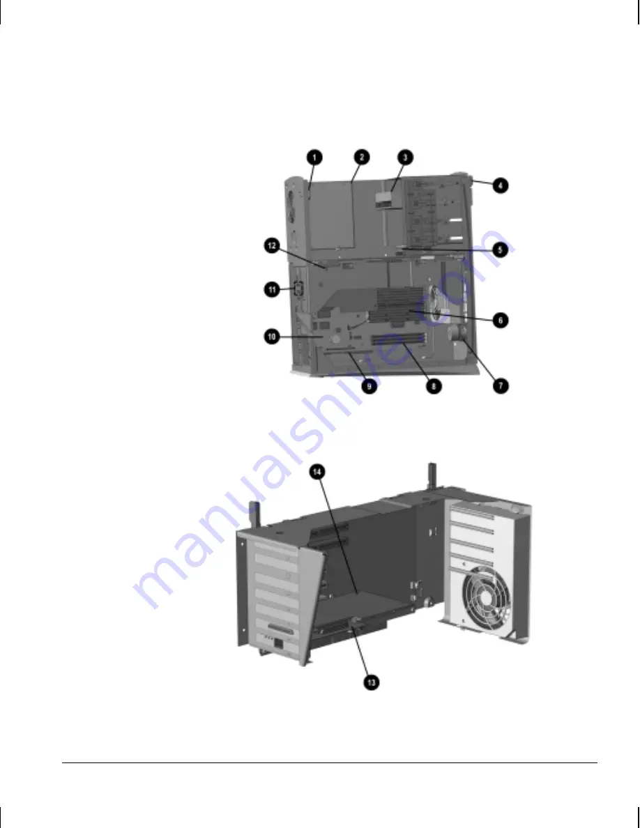
Internal Components in Minitower Models

Expansion Boards in Minitower Models

Содержание Deskpro AP240

Страница 1: ...Reference Guide Compaq Deskpro Workstation AP240...

Страница 2: ...ows Windows NT and other names of Microsoft products referenced herein are trademarks or registered trademarks of Microsoft Corporation Intel and Pentium are registered trademarks of Intel Corporation...

Страница 3: ...ard 1 26 Turning Off Your Workstation 1 27 chapter 2 Software Installing Your Operating System 2 1 Installing or Upgrading Device Drivers for Windows NT Workstation 4 0 2 1 Converting to NTFS 2 2 Meth...

Страница 4: ...Lock 3 13 Using the Smart Cover FailSafe Key 3 13 Security Lock 3 13 Fingerprint Identification Technology 3 14 Fault Notification and Recovery 3 14 Pentium II and Pentium III Fault Prediction and Pre...

Страница 5: ...rkstation Serviceability Features 5 1 Removing the Workstation Cover 5 1 Tilting the Drive Cage 5 3 Raising the Expansion Card Cage 5 5 Sliding Out the System Board Tray 5 7 Installing Additional Memo...

Страница 6: ...ing a Blank Drive Bezel 6 17 Installing a CD ROM DVD ROM or Tape Drive 6 18 Installing a 3 5 Inch Drive into a 5 25 Inch Drive Bay 6 20 Removing a Drive from the Drive Cage 6 24 Smart Cover Lock 6 24...

Страница 7: ...ntelligent Manageability Features 8 16 Compaq Configuration Record Utility 8 16 Contacting Compaq Customer Support 8 17 appendix A Regulatory Compliance Notices A 1 appendix B Electrostatic Discharge...

Страница 8: ...s that vary depending on the model Intel Pentium III processor Intel 820 chipset with ITE 8889 PCI ISA bridge or Intel 440BX PIIX 4E AGP chipset Direct Rambus DRAM RDRAM or synchronous DRAM SDRAM syst...

Страница 9: ...ional drives and one internal 3 5 inch one third height bay for a hard drive Compaq minitower chassis including five PCI expansion slots and two ISA expansion slots with an AGP slot on the system boar...

Страница 10: ...Tracking and Security Fault Notification and Recovery and Software Updating and Management Software controllable Smart Cover Lock Microsoft Windows NT Version 4 0 operating system Microsoft Internet E...

Страница 11: ...1 4 Workstation Features Front Panel Components Intel 820 Chipset Desktop Front Panel Components Minitower Front Panel Components...

Страница 12: ...6 CD ROM Drive Tray Loads a CD ROM into the drive 7 CD ROM Drive Busy Indicator Flashes when the drive is reading a CD ROM 8 CD ROM Emergency Eject Hole Allows you to eject a CD ROM in the event of a...

Страница 13: ...1 6 Workstation Features Rear Panel Components Intel 820 Chipset Desktop Rear Panel Components Minitower Rear Panel Components...

Страница 14: ...5 cable 5 Line In Audio Connector Connects a device that supplies sound such as a tape deck or CD player 6 Wide UltraSCSI Connector Connects external SCSI devices 7 Mouse Connector Connects the mouse...

Страница 15: ...ipset Internal Components in Desktop Models Expansion Cards in Desktop Models The position of the expansion card cage in this illustration is for demonstration purposes only Be sure to rest the expans...

Страница 16: ...D ROM drive 4 Diskette drive 5 Processor 6 Internal speaker 7 Serial number 8 Smart Cover Lock 9 Embedded audio connectors Smart Cover Sensor Graphics controller Rambus inline memory module RIMM socke...

Страница 17: ...1 10 Workstation Features Minitower Internal Components Intel 820 Chipset Internal Components in Minitower Models Expansion Cards in Minitower Models...

Страница 18: ...age upside down rather than on either side of the cage 1 Smart Cover Lock 2 Power supply 3 CD ROM drive 4 Diskette drive 5 Internal hard drive 6 Processor 7 Internal speaker 8 Rambus inline memory mod...

Страница 19: ...1 12 Workstation Features Desktop Front and Rear Panel Components Intel BX Chipset Desktop Front Panel Components...

Страница 20: ...in the event of a power failure 8 CD ROM Eject Button Ejects a CD ROM from the drive 9 Dual State Power Button Switches the workstation between suspend and wakeup modes can be configured as an on off...

Страница 21: ...rounding plug The grounding plug is an important safety feature Plug the power cord into a grounded earthed electrical outlet that is easily accessible at all times Disconnect power from the workstati...

Страница 22: ...s select models 7 Mouse Connector Connects the mouse green colored icon 8 Monitor Connector Connects a monitor 9 Voltage Select Switch Switches voltage between 115V and 230V to match geographical requ...

Страница 23: ...1 16 Workstation Features Minitower Front and Rear Panel Components Intel BX Chipset Minitower Front Panel Components...

Страница 24: ...when the drive is reading a CD ROM 8 CD ROM Eject Button Ejects a CD ROM from the drive 9 Dual State Power Button Switches the workstation between suspend and wakeup modes can be configured as an on o...

Страница 25: ...ounding plug The grounding plug is an important safety feature Plug the power cord into a grounded earthed electrical outlet that is easily accessible at all times Disconnect power from the workstatio...

Страница 26: ...nects a parallel device such as a parallel printer 7 Serial Connectors Connect serial devices such as a serial mouse and scanner 8 Smart Cover Lock Prevents unauthorized access to the internal compone...

Страница 27: ...1 20 Workstation Features Desktop Internal Components Intel BX Chipset Internal Components in Desktop Models Expansion Boards in Desktop Models...

Страница 28: ...d cage upside down rather than on either side of the cage 1 Power supply 2 Internal hard drive 3 CD ROM drive 4 Diskette drive 5 Processor 6 Internal speaker 7 Smart Cover Lock 8 Smart Cover Sensor 9...

Страница 29: ...1 22 Workstation Features Minitower Internal Components Intel BX Chipset Internal Components in Minitower Models Expansion Boards in Minitower Models...

Страница 30: ...d cage upside down rather than on either side of the cage 1 Smart Cover Lock 2 Power supply 3 CD ROM drive 4 Diskette drive 5 Internal hard drive 6 Processor 7 Internal speaker 8 Dual inline memory mo...

Страница 31: ...ard drive activity Suspend Blinking green with 1 blink every second Off Suspend to disk Blinking green with 1 blink every 2 seconds Off Error Conditions Power Light Hard Drive Activity Light Thermal s...

Страница 32: ...n On ROMPaq diskette not present is bad or drive not ready A Boot Block Recovery message appears Intel 820 chipset when using an embedded graphics controller or a PCI or AGP graphics controller card C...

Страница 33: ...ftware you are using 4 Application Used like the right mouse button to open pop up menus in a Microsoft Office application May perform other functions in other software applications 5 Editing keys Inc...

Страница 34: ...art menu The workstation will automatically shut down WARNING To reduce the risk of personal injury from electrical shock and or hot surfaces before you open the workstation cover for any reason Be su...

Страница 35: ...RN OFF THE WORKSTATION UNTIL THE PROCESS IS COMPLETE Turning off the workstation during the installation process might damage the software that runs the workstation When the Welcome to Windows screen...

Страница 36: ...t have a CD ROM drive other means of installation such as a network share will be needed CAUTION The following procedures will remove all of the software applications and data files from your hard dri...

Страница 37: ...sert the bootable MS DOS diskette into the diskette drive and turn on or restart the workstation 2 At the MS DOS Prompt run FDISK and press Enter 3 When prompted select large drive support 4 From the...

Страница 38: ...e installation process begins automatically 2 Let Windows NT create the primary partition using the maximum capacity of the hard drive 3 When prompted select NTFS to format the hard drive 4 Read and f...

Страница 39: ...The Compaq Restore CD offers easy deployment and recovery of your Deskpro system software Along with the operating system CD the Compaq Restore CD enables you to restore the original Deskpro system so...

Страница 40: ...which allows the workstation to boot the operating system when the power on password is enabled with or without a keyboard or mouse attached When attached to the system the keyboard and mouse remain l...

Страница 41: ...r disable removable media write ability Solve system configuration errors detected but not automatically fixed during the Power On Self Test POST Replicate your system setup by saving system configura...

Страница 42: ...ress the Enter key A choice of five headings appears in the Computer Setup Utilities menu File Storage Security Power and Advanced 4 Using the arrow keys or the Tab key select the option you want and...

Страница 43: ...umber Set Time and Date Allows you to set system time and date Save to Diskette Saves system configuration including CMOS to a blank formatted 1 44 MB diskette Restore from Diskette Restores system co...

Страница 44: ...ices IDE Drive Timing Allows you to set hard drive to Ultra DMA Ultra ATA Enhanced DMA or PIO mode operation Note The configuration of your workstation determines which selections appear under this op...

Страница 45: ...te This selection will appear only if a power on password is set Smart Cover Enables disables Smart Cover Sensor and Cover Lock lists most recent cover removal Feature supported on select models only...

Страница 46: ...enabled operating systems Timeouts Allows you to disable or manually select timeout values for the system and or all attached IDE hard drives Note This option is not available under ACPI enabled oper...

Страница 47: ...like to turn on power to the workstation using the switch on the power strip set this option to on Note If you turn off power to your workstation using the switch on a power strip you will not be abl...

Страница 48: ...RST during a warm reboot enable disable PCI VGA palette snooping which sets the VGA palette snooping bit in PCI configuration space this is only needed with more than one graphics controller installed...

Страница 49: ...be the boot or primary VGA controller These options should be used by advanced users only Compaq Diagnostics for Windows Compaq Diagnostics for Windows is a component of Intelligent Manageability that...

Страница 50: ...ted category click More in the Information Level box 4 Review and print this information and if necessary discuss it with your authorized Compaq reseller or service provider To print the information c...

Страница 51: ...e diagnostic software will prompt you for input during tests that require it Some tests require interaction and will display errors or halt testing if selected in conjunction with Unattended Mode 4 Cl...

Страница 52: ...ecuted even if the workstation will not boot to an operating system The time required to execute the test depends on the manufacturer and size of the hard drive in most cases the test will take approx...

Страница 53: ...completion code should be recorded and reported to your service provider for help in diagnosing the workstation problem Accessing DPS Through Computer Setup When the workstation does not power on pro...

Страница 54: ...lp in diagnosing the workstation problem Workstation Reference Library CD Be sure to browse the Workstation Reference Library CD The CD contains detailed product information about your graphics contro...

Страница 55: ...ility between Intelligent Manageability and these products Intelligent Manageability is an important aspect of our broad commitment to providing you with lifecycle management solutions and services to...

Страница 56: ...oftware image Using a Preboot Execution Environment PXE based tool such as Platinum AutoConfigure formerly Intel LANDesk Configuration Manager to replace the preinstalled software with a customized so...

Страница 57: ...oftware or drivers To initiate Remote System Installation press F12 when the F12 Network Service Boot message appears in the lower right corner of the Compaq logo screen Follow the instructions on the...

Страница 58: ...ing the Compaq Computer Setup Utilities See Chapter 2 Software for more information and instructions Remotely using the Compaq Remote Security Management software This software enables the secure cons...

Страница 59: ...u Power On Password Prevents use of the workstation until the password is entered This can apply to both initial workstation startup and restarts From the Compaq Computer Setup Utilities menu Setup Pa...

Страница 60: ...ifies end user and system administrator For information on enabling Memory Change Alerts refer to the online Intelligent Manageability Guide Ownership Tag Displays ownership information as defined by...

Страница 61: ...to log in to all network systems to perform maintenance without having to know the power on password even if one has been established Establishing a Setup Password Using Computer Setup Establishing a...

Страница 62: ...he F10 key while the message is displayed you must turn the workstation off then on again to access the utility 3 Select Security then Power On Password and follow the instructions on the screen 4 Bef...

Страница 63: ...ssword new password Type carefully for security reasons the characters you type do not appear on the screen 3 Press the Enter key The new password takes effect the next time you turn on the workstatio...

Страница 64: ...puter Setup National Keyboard Delimiter Characters Each keyboard is designed to meet country specific requirements The syntax and keys that you use for changing or deleting your password depend on the...

Страница 65: ...estarted the screen displays a message indicating that the workstation cover or side panel has been removed Level 2 Setup Password When the workstation is restarted the screen displays a message indic...

Страница 66: ...d The setup password prevents unauthorized access to the Computer Setup utility Locking the Smart Cover Lock To activate and lock the Smart Cover Lock complete the following steps 1 Turn on or restart...

Страница 67: ...and Exit Using the Smart Cover FailSafe Key If you enable the Smart Cover Lock and cannot enter your password to disable the lock you will need a Smart Cover FailSafe Key to open the workstation cover...

Страница 68: ...cription of the fault and any recommended actions You can then view current system health by using the Compaq Management Agent If the workstation is connected to a network managed by Compaq Insight Ma...

Страница 69: ...r Self Monitoring Analysis and Reporting Technology SMART SMART is the industry standard technology pioneered by Compaq and originally called IntelliSafe that allows you to prevent data loss and minim...

Страница 70: ...or PD CD backup upon receiving notice of an impending SMART hard drive failure The Seagate Backup Exec SMART Client works with Seagate Backup Exec tape backup software on the server or with Seagate B...

Страница 71: ...l tools for managing and updating software on workstations Insight Manager LC System Software Manager and Remote Management Setup Utilities Using Insight Manager LC you can monitor a workgroup of work...

Страница 72: ...Compaq Web site at www compaq com support files index html The following sections provide information on using these utilities to accomplish various remote management functions including ROM flash cha...

Страница 73: ...m Compaq are digitally signed to ensure authenticity and minimize potential corruption The ROM firmware includes a Boot Block that is protected during the flash process and allows the Deskpro Workstat...

Страница 74: ...nd flashes the three keyboard lights on and off two times A Boot Block recovery mode message will appear on the screen Intel 820 chipset only For more information on diagnostic lights see Chapter 1 Wo...

Страница 75: ...ote Security Management also requires an established setup password For more information about the Remote Management Setup software and enabling Remote Security Management refer to the online Remote M...

Страница 76: ...4 Select Remote Wakeup 5 Change the value to ON 6 Click OK to save and apply changes then click OK to exit the Network dialog For more information on using Remote Wakeup and Remote Shutdown refer to...

Страница 77: ...instructions on the screen Power Management Power Management is a feature that saves energy by shutting down certain components of the workstation when they are not in use saving energy without having...

Страница 78: ...install corresponding Compaq device drivers and utilities to ensure all features are supported and functioning properly Microsoft Windows 3 1 IBM OS 2 A version of Microsoft Windows or Microsoft Wind...

Страница 79: ...orth America only Compaq part number 272505 xxx You can purchase a yearly subscription that delivers up to 12 monthly CD ROMs Compaq part number 183426 xxx The annual subscription ensures your continu...

Страница 80: ...sed Enterprise Management Intel s Wired for Management SNMP and Net PC technologies Microsoft Intel Hewlett Packard Novell Seagate and other industry leaders work closely with Compaq to integrate thei...

Страница 81: ...Interface DMI 2 0 Remote System Installation Remote Wakeup and Remote Shutdown ACPI Ready Hardware Compaq Management Solutions Partners Program Compaq delivers desktop management solutions through the...

Страница 82: ...pter includes information about the general installation sequence for a workstation and about when to reconfigure the workstation to ensure that it recognizes the newly installed equipment Installatio...

Страница 83: ...uipment Before beginning these procedures ensure that you are discharged of static electricity by briefly touching a grounded metal object Refer to Appendix B Electrostatic Discharge for more informat...

Страница 84: ...drives as device 0 primary drive or device 1 secondary drive The workstation recognizes device 0 as the drive connected to the short segment of the drive cable farthest from the system board and devi...

Страница 85: ...ines The Wide Ultra2 SCSI or Wide UltraSCSI host adapter supports up to 15 wide SCSI devices Every SCSI device must have a unique identification ID number 0 15 The SCSI host adapter identifies signals...

Страница 86: ...I device is connected to the external SCSI connector on the rear panel of the workstation that device becomes the end of the SCSI chain and must be terminated The system accommodates a combination of...

Страница 87: ...SCSI device 1 Workstations with 2 peripheral SCSI cables without termination must have termination enabled on the last device 2 Workstations with 3 and 4 peripheral SCSI cables come with a terminator...

Страница 88: ...n Post Messages Enabled mode Press Ctrl A when the Press Ctrl A for SCSISelect Utility message appears during POST In Post Messages Disabled mode When the Compaq logo screen appears press any key to e...

Страница 89: ...ools or thumbscrews WARNING Before removing the workstation cover ensure that the workstation is turned off and that the power cord is disconnected from the electrical outlet If you have not already d...

Страница 90: ...es on the sides of the desktop workstation toward the front of the workstation 5 Slide the cover forward about 1 inch 2 5 cm then lift it up and off the unit Removing the Desktop Workstation Cover CAU...

Страница 91: ...the drive power and signal cables When installing optional drives you must install guide screws to ensure the drive will line up correctly in the drive cage Compaq has provided extra guide screws ins...

Страница 92: ...ove the workstation cover 5 Grasp the top of the tilt drive cage and rotate it to its upright position If the tilt drive cage catches when you are rotating it slide it to the right to release it from...

Страница 93: ...Before removing the workstation cover ensure that the workstation is turned off and that the power cord is disconnected from the electrical outlet 1 If you have locked the Smart Cover Lock use Comput...

Страница 94: ...rd The built in catch on Intel 820 chipset based models secures the cage and prevents it from damaging components on the system board This is service position 2 Raising the Expansion Card Cage To reco...

Страница 95: ...t Cover Lock use Computer Setup to unlock the lock and disable the Smart Cover Sensor 2 Shut down the operating system properly then turn off the workstation and any external devices 3 Disconnect the...

Страница 96: ...d 184 pin PC600 PC700 or PC800 compliant RAMBUS memory modules depending on the model They must also contain the mandatory Joint Electronic Device Engineering Council JEDEC Serial Presence Detect SPD...

Страница 97: ...metals in contact with each other CAUTION Static electricity can damage the electronic com ponents of the workstation or optional cards Before beginning these procedures ensure that you are discharged...

Страница 98: ...stall the modules following the numerical order of the sockets A memory module can be installed in only one way Match the notch on the module with the tab on the memory socket Push the module down int...

Страница 99: ...into the socket 5 Repeat step 4 for any additional modules that you want to install 6 Replace the workstation cover 7 If you normally lock the Smart Cover Lock use Computer Setup to relock the lock an...

Страница 100: ...tation contains expansion slots as follows Expansion Slots in the Desktop Expansion Card Cage 1 PCI ISA Peripheral Component Interconnect Industry Standard Architecture shared expansion slots 2 PCI ex...

Страница 101: ...utlet 3 Remove the workstation cover 4 Raise the expansion card cage by lifting and locking the two green levers You do not need to remove the cage from the chassis 5 Locate the correct vacant slot in...

Страница 102: ...disconnect any cables attached to the expansion card 6 Remove the screw at the side of the expansion slot You will need to slide the system board tray backward a short distance to access the screws fo...

Страница 103: ...ts properly in the expansion card slot 12 Replace the screw at the side of the expansion slot 13 Using the two green levers lower and secure the expansion card cage into the workstation chassis Be sur...

Страница 104: ...e diskette and hard drive cables from the drives For optimal performance connect hard drives to the primary IDE controller Connect expansion devices such as IDE CD ROM tape and diskette drives to the...

Страница 105: ...ve Signal Cables When connecting drive signal cables note that the cables connect to the expansion card cage as shown in the following illustration Drive Signal Cable Connectors 1 Diskette drive 2 CD...

Страница 106: ...down the operating system properly turn off the workstation and any external devices then disconnect the power cord from the electrical outlet 3 Remove the workstation cover and set it with its top d...

Страница 107: ...nstall two guide screws on each side of the drive Some options use M3 metric thread hardware Extra guide screws are provided on the front of the chassis under the front bezel The Compaq supplied metri...

Страница 108: ...m the drive cage Excessive shock can damage the drive 5 With the drive rotated to its upright position connect the drive power 1 and signal 2 cables and if it is a CD ROM drive connect the audio cable...

Страница 109: ...gure the workstation if necessary Refer to Chapter 2 Software for more information If you normally lock the Smart Cover Lock use Computer Setup to relock the lock and enable the Smart Cover Sensor Ins...

Страница 110: ...the adapter with the screws provided The 5 25 inch adapter is included with the optional hard disk drive For more information about the 5 25 inch adapter refer to the documentation included in the op...

Страница 111: ...with the guide slots in the drive cage You may need to tilt the drive cage forward to its upright position to secure the green latch Installing an Adapter with a 3 5 Inch Drive CAUTION Before completi...

Страница 112: ...stallation Guidelines for more information Connecting the Drive Cables 7 Gently rotate the drive cage back into the workstation chassis CAUTION When returning the drive cage to its normal position use...

Страница 113: ...the Drive Cage 1 If you have locked the Smart Cover Lock use Computer Setup to unlock the lock and disable the Smart Cover Sensor 2 Shut down the operating system properly turn off the workstation di...

Страница 114: ...e Drive Cage 6 Remove the drive from the drive cage and store in antistatic packaging Smart Cover Lock The Smart Cover Lock is a software controllable cover lock This lock prevents unauthorized access...

Страница 115: ...rd CAUTION The Smart Cover FailSafe Key is a specialized tool available from Compaq Be prepared order this key before you need one You can obtain the FailSafe Key by any one of the following methods C...

Страница 116: ...e Key remove the tamper proof screws securing the Smart Cover Lock to the chassis Removing the Smart Cover Lock Screws 3 Remove the workstation cover To reattach the Smart Cover Lock secure the lock i...

Страница 117: ...sington Microware Limited or Compaq authorized dealers resellers and service providers Ask for the Kensington MicroSaver Security System Model 64068 1 Loop the cable around a heavy fixed object to whi...

Страница 118: ...t disassemble crush puncture short external contacts or dispose of in fire or water Replace only with the Compaq spare designated for this product Batteries battery packs and accumulators should not b...

Страница 119: ...ard as shown in the following illustration Battery and Battery Holder 4 Lift the battery out of its holder Removing the Coin Cell Battery 5 Slide the replacement battery into position positive side up...

Страница 120: ...rkstation and turn on power to the workstation 8 Reset the date and time your passwords and any special system setups using Compaq Computer Setup Refer to Chapter 2 Software If you normally lock the S...

Страница 121: ...turned off and that the power cord is disconnected from the electrical outlet 1 If you have locked the Smart Cover Lock use Computer Setup to unlock the lock and disable the Smart Cover Sensor 2 Shut...

Страница 122: ...on access panel provides additional information including information about diagnosing workstation conditions using the power and hard drive LEDs Raising the Expansion Card Cage The expansion card cag...

Страница 123: ...osition to electrically disconnect it from the system board This is service position 1 6 Raise the expansion card cage to engage the built in catch that holds the cage up and away from the system boar...

Страница 124: ...nnected from the electrical outlet 1 If you have locked the Smart Cover Lock use Computer Setup to unlock the lock and disable the Smart Cover Sensor 2 Shut down the operating system properly then tur...

Страница 125: ...screw securing the system board tray grasp the back edge of the tray and slide it straight out of the chassis When reassembling the workstation be sure to reinstall the green thumbscrew to secure the...

Страница 126: ...er capacity RIMMs All slots must be occupied by either memory modules at least one or continuity modules For proper system operation the RIMMs must be industry standard 184 pin PC600 PC700 or PC800 co...

Страница 127: ...h x4 SDRAM are not supported the system will not start using unsupported DIMMs Memory Module Installation CAUTION Your memory module sockets have gold metal contacts When upgrading your memory it is i...

Страница 128: ...nternal system components to cool before touching 4 Open both latches of the memory module socket 1 and insert the memory module into the socket 2 Begin by installing a module into the socket nearest...

Страница 129: ...tinuity module from the socket then insert the RIMM into the socket 5 Repeat step 4 for any additional modules that you want to install 6 Replace the workstation access panel 7 If you normally lock th...

Страница 130: ...workstation contains expansion slots as follows Expansion Slots in the Minitower Expansion Card Cage 1 ISA Industry Standard Architecture expansion slots 2 PCI Peripheral Component Interconnect expans...

Страница 131: ...d any external devices then disconnect the power cord from the power outlet 3 Remove the workstation access panel 4 Raise the expansion card cage into service position 2 You do not need to remove the...

Страница 132: ...d cage into service position 2 You do not need to remove the cage from the chassis If installing an expansion card skip to step 10 5 To remove an expansion card disconnect any cables attached to the e...

Страница 133: ...board so that the whole connector seats properly in the expansion card slot 12 Replace the screw at the side of the expansion slot 13 Using the two green levers lower and secure the expansion card ca...

Страница 134: ...he diskette and hard drive cables from the drives For optimal performance connect hard drives to the primary IDE controller Connect expansion devices such as IDE CD ROM tape and diskette drives to the...

Страница 135: ...ve Signal Cables When connecting drive signal cables note that the cables connect to the expansion card cage as shown in the following illustration Drive Signal Cable Connectors 1 Primary IDE hard dri...

Страница 136: ...ck and disable the Smart Cover Sensor 2 Shut down the operating system properly then turn off the workstation and disconnect the power cord from the electrical outlet 3 Remove the workstation access p...

Страница 137: ...Cover Sensor 2 Shut down the operating system properly then turn off the workstation and disconnect the power cord from the electrical outlet 3 Remove the workstation access panel and front bezel 4 Sq...

Страница 138: ...outlet and remove the workstation access panel and front bezel 3 Install two guide screws on each side of the drive Some options use M3 metric thread hardware Extra guide screws are provided on the f...

Страница 139: ...nd if it is a CD ROM or DVD ROM drive connect the audio cable 3 The other end of the audio cable 3 should be connected to the audio connector on the expansion card cage Connecting the Drive Cables Con...

Страница 140: ...you normally lock the Smart Cover Lock use Computer Setup to relock the lock and enable the Smart Cover Sensor Installing a 3 5 Inch Drive into a 5 25 Inch Drive Bay 1 If you have locked the Smart Cov...

Страница 141: ...ter with the screws provided The 5 25 inch adapter is included with the optional hard disk drive For more information about the 5 25 inch adapter refer to the documentation included in the option kit...

Страница 142: ...l the drive and adapter in the desired drive bay by sliding it into the front of the drive cage secure the drive with the green latch Be sure the guide screws line up with the guide slots in the drive...

Страница 143: ...kstation access panel 9 Reconfigure the workstation if necessary Refer to Chapter 2 Software for more information If you have installed a second diskette drive B you will need to reconfigure the works...

Страница 144: ...g Smart Cover Lock The Smart Cover Lock is a software controllable cover lock This lock prevents unauthorized access to the internal components when the Smart Cover Lock and setup password are enabled...

Страница 145: ...ng information Call the appropriate number listed in the warranty To open the workstation access panel 1 Shut down the operating system properly turn off the workstation and disconnect the power cord...

Страница 146: ...el the rear panel of the workstation accommodates a cable lock so that the workstation can be physically secured to a work area The cable lock can be purchased from Kensington Microware Limited or Com...

Страница 147: ...e Guide 6 27 2 Insert the cable lock end of the cable through the loop end of the cable 3 Insert the lock into the appropriate slot on the rear of the workstation and lock with the key Installing a Ca...

Страница 148: ...o not disassemble crush puncture short external contacts or dispose of in fire or water Replace only with the Compaq spare designated for this product Batteries battery packs and accumulators should n...

Страница 149: ...ard as shown in the following illustration Battery and Battery Holder 4 Lift the battery out of its holder Removing the Coin Cell Battery 5 Slide the replacement battery into position positive side up...

Страница 150: ...r to Chapter 2 Software If you normally lock the Smart Cover Lock use Computer Setup to relock the lock and enable the Smart Cover Sensor Removing the Workstation Base If necessary you can remove the...

Страница 151: ...e workstation is powered off Depending on the NIC model these alerts may include system BIOS hang operating system hang processor missing operating temperature exceeded chassis intrusion Remote Wakeup...

Страница 152: ...us Lights Select Ethernet network interface controllers include network status lights The link light illuminates when the system is physically connected to an active network The activity light illumin...

Страница 153: ...ems cannot transmit and receive simultaneously If necessary you can disable the autosensing capabilities and force the system to operate in one mode only 1 Select the Network icon located in the Contr...

Страница 154: ...etwork Device drivers are supplied for the Microsoft Windows NT version 4 0 operating system If you are using another operating system device drivers may be installed from diskettes included with the...

Страница 155: ...l display the error message To manually switch to the POST Messages Enabled mode during POST press any key except F10 or F12 The default mode is POST Message Disabled The speed at which the workstatio...

Страница 156: ...ight is on Turn up the brightness and contrast controls of the monitor if the monitor is dim Press and hold any key If the system beeps then your keyboard should be operating correctly Check all cable...

Страница 157: ...nal Press and hold the power button until the workstation turns off Workstation date and time display is incorrect RTC real time clock battery may need to be replaced Battery life is approximately 5 y...

Страница 158: ...ion cover or access panel Smart Cover Lock featured on some workstations is locked Unlock the Smart Cover Lock using Computer Setup F10 Setup The Smart Cover FailSafe Key a device for manually disabli...

Страница 159: ...hecking click Check Now Diskette is incorrectly inserted Remove diskette and reinsert Drive button is not pushed in Push in drive button Software program is damaged Check the program diskettes Drive c...

Страница 160: ...read a diskette Diskette is not formatted Format the diskette You are using the wrong diskette type for the drive type Check the type of drive you are using and use the correct diskette type Drive not...

Страница 161: ...itor is incorrectly set Set the monitor s RGB input switch to 75 ohms and if there is a sync switch set it to External System ROM is bad system is running in Failsafe Boot Block mode indicated by one...

Страница 162: ...onitor Blurry video or requested resolution cannot be set If the graphics controller was upgraded the correct graphics drivers may not be loaded Install the video drivers on the diskette included in t...

Страница 163: ...s and solutions listed in the following table Problem Cause Solution Printer will not print Printer is not turned on and online Turn the printer on and make sure it is online The correct printer drive...

Страница 164: ...not recognized as part of the workstation system The workstation needs to be reconfigured to recognize the device Follow the reconfiguration instructions above Cable s of new external device are loose...

Страница 165: ...er Network controller is disabled Run Computer Setup and enable network controller Network status link light does not turn on or flashes No active network is detected Check cabling and network equipme...

Страница 166: ...at the other end are operating correctly The network controller is defective Contact your Compaq authorized service provider Network controller interrupt is shared with an expansion card Under the Co...

Страница 167: ...etwork controller stopped working without apparent cause The files containing the network drivers are corrupted Reinstall the network drivers using the Compaq Restore CD The cable is not securely conn...

Страница 168: ...alled correctly Check that the memory modules have been installed correctly and that proper modules are used Insufficient memory error during operation Too many Terminate and Stay Resident programs TS...

Страница 169: ...is not loaded Drive is not connected properly or not properly configured Refer to the documentation that came with the optional device Movie will not play in the DVD drive Movie may be regionalized f...

Страница 170: ...e detailed information refer to the online Intelligent Manageability guide and Chapter 3 Desktop Management Compaq Configuration Record Utility Compaq Configuration Record Utility is an online informa...

Страница 171: ...artup files The utility then combines this information with information on the hardware configuration to deliver a comprehensive view of the workstation Contacting Compaq Customer Support For help and...

Страница 172: ...hese limits are designed to provide reasonable protection against harmful interference in a residential installation This equipment generates uses and can radiate radio frequency energy and if not ins...

Страница 173: ...ted States only This device complies with Part 15 of the FCC Rules Operation is subject to the following two conditions 1 This device may not cause harmful interference and 2 This device must accept a...

Страница 174: ...the Commission of the European Community Compliance with these directives implies conformity to the following European Norms the equivalent international standards are in brackets EN55022 CISPR 22 Ele...

Страница 175: ...agement section of Chapter 3 Desktop Management The power management feature of your workstation is compatible with any network operating system or environment that supports APM1 2 This means the user...

Страница 176: ...t the beam is totally enclosed during all modes of customer operation and maintenance WARNING To reduce the risk of exposure to hazardous radiation Do not try to open the laser device enclosure There...

Страница 177: ...PRODUCT This label appears on a laser device installed in your product If you have an LS 120 drive this label is located next to the Class 1 Laser Product label on your system Laser Information Laser...

Страница 178: ...recharge the battery Do not expose to temperatures higher than 60 C 140 F Do not disassemble crush puncture short external contacts or dispose of in fire or water Replace only with the Compaq spare d...

Страница 179: ...ostatic Damage To prevent electrostatic damage observe the following precautions Avoid hand contact by transporting and storing products in static safe containers Keep electrostatic sensitive parts in...

Страница 180: ...s To provide proper ground wear the strap snug against the skin Use heelstraps toestraps or bootstraps at standing workstations Wear the straps on both feet when standing on conductive floors or dissi...

Страница 181: ...rvice provider General Requirements The requirements listed below are applicable to all countries The length of the power cord must be at least 6 0 feet 1 8 m and a maximum of 12 feet 3 7 m The power...

Страница 182: ...rements Country Accredited Agency Applicable Note Argentina IRAM 1 Australia EANSW 1 Austria OVE 1 Belgium CEBC 1 Canada CSA 2 Chile N A 4 China CCEE 5 Denmark DEMKO 1 Finland SETI 1 France UTE 1 Germ...

Страница 183: ...tor 1 0 mm2 conductor size Wall plug must be a two pole grounding type with a Japanese Industrial Standard C8303 7A 125V configuration 4 Flexible cord must be Type SVT No 16 AWG 3 cconductor Wall plug...

Страница 184: ...into the workstation by blocking the front vents or air intake Do not place the keyboard with the keyboard feet down directly against the front of the desktop unit as this also restricts airflow Neve...

Страница 185: ...posing the drive to sudden changes in temperature as condensation may form inside the unit If the temperature suddenly changes while the drive is on wait at least one hour before you turn off the powe...

Страница 186: ...to protect the drive while in transit Do not use a diskette on which you have stored or plan to store data 4 Turn off the workstation and external devices 5 Disconnect the power cord from the electric...

Страница 187: ...Probable Cause Recommended Action 101 Option ROM Error 1L 1S System ROM checksum 1 Verify the correct ROM 2 Flash the ROM if needed 3 If an expansion card was recently added remove it and see if the...

Страница 188: ...time clock battery may need to be replaced Battery life is approximately 5 years CMOS jumper may not be properly installed Reset the date and time under Control Panel If the problem persists replace...

Страница 189: ...with matched sets 207 ECC Corrected Single Bit Errors in DIMM SIMM Pair s x x in Memory Module Socket s y y 2S Single Bit ECC error 1 Verify proper memory module type 2 Try another memory socket 3 Re...

Страница 190: ...licts with another device Reset the IRQ 404 Parallel Port Address Conflict Detected 2S Both external and internal ports are assigned to parallel port X 1 Remove any parallel port expansion cards 2 Cle...

Страница 191: ...tape drives 3 Clear CMOS 610 External Storage Device Failure None External tape drive not connected Reinstall tape drive or press F1 and allow system to reconfigure without the drive 611 Primary Flop...

Страница 192: ...ection 1151 Serial Port 1 Address Conflict Detected 2S Both external and internal serial ports are assigned to COM1 1 Remove any serial port expansion cards 2 Clear CMOS 3 Reconfigure card resources a...

Страница 193: ...ror message Run the Drive Protection System test if available 2 Apply firmware patch if applicable 3 Back up contents and replace hard drive 1721 SMART SCSI Hard Drive Detects Imminent Failure None Ha...

Страница 194: ...p F10 Setup 1780 Disk 0 Failure None Hard drive format error 1 Run Computer Setup F10 Setup 2 Clear CMOS 3 Check cables jumper settings 4 Run hard drive diagnostics 5 Disconnect additional drives 6 Ru...

Страница 195: ...6 Run the Drive Protection System test if available 7 Replace the hard drive 8 Replace the system board 1790 Disk 0 Error None Hard drive error or wrong drive type 1 Run Computer Setup F10 Setup 2 Cl...

Страница 196: ...e hard drive 9 Replace the system board 1792 Secondary Disk Controller Failure None Hard drive circuitry error 1 Run Computer Setup F10 Setup 2 Clear CMOS 3 Check cable seating jumper settings 4 Run h...

Страница 197: ...Power on successful None Flashing Caps Lock LED on Keyboard 1L 2S Graphics controller not present or incorrectly initialized 1 Following directions in Appendix G to clear CMOS 2 If graphics card has b...

Страница 198: ...EXE SNZERO EXE Flashing Power and Hard Drive Green LEDs None Unseated riser board 1 Remove riser board 2 Wipe connector 3 Reinstall refer to Chapter 5 Upgrading the Desktop Workstation or Chapter 6 U...

Страница 199: ...he Solving Memory Problems section of this guide Red Power LED Blinks Four Times per Second None Workstation overheated 1 Install workstation cover or access panel if necessary 2 Ensure that workstati...

Страница 200: ...8 in 18 60 in 51 44 cm 21 29 cm 47 24 cm Approximate Weight Desktop Model Minitower Model 32 0 lb 14 5 kg Weight Supported maximum distributed load 100 0 lb 45 5 kg Temperature Range Operating Nonoper...

Страница 201: ...rating Voltage Range Rated Voltage Range Rated Line Frequency 90 132 VAC 100 127 VAC 47 63 Hz 180 264 VAC 220 240 VAC 47 63 Hz Power Output 200 W 200 W Rated Input Current maximum 6 A 3 A Heat Dissipa...

Страница 202: ...ght Supported maximum distributed load 100 0 lb 45 5 kg Temperature Range Operating Nonoperating 50 to 95 F 4 to 140 F 10 to 35 C 20 to 60 C Power Supply Operating Voltage Range Rated Voltage Range Ra...

Страница 203: ...ired to access Computer Setup F10 Setup and any other information on the workstation When you establish both passwords only the setup password will give you access to Computer Setup F10 Setup When bot...

Страница 204: ...r hot surfaces be sure to disconnect the power cord from the wall outlet and allow the internal system components to cool before touching CAUTION When the workstation is plugged in the power supply al...

Страница 205: ...g it 6 Replace the workstation cover or access panel 7 Reconnect the external equipment 8 Plug in the workstation and turn on power Allow the operating system to start This clears the current password...

Страница 206: ...2 3 of E50 for at least one minute 3 After waiting at least one minute replace the jumper on pins 1 2 4 Reassemble and restart the workstation Your password is erased from system memory When you rest...

Страница 207: ...outlet and allow the internal system components to cool before touching CAUTION When the workstation is plugged in the power supply always has voltage applied to the system board even when the unit is...

Страница 208: ...the Using Computer Setup section below for further instructions Using Computer Setup to Reset CMOS To reset CMOS you must first access the Computer Setup F10 Setup Utilities menu When the Computer Set...

Страница 209: ...her instructions on reestablishing passwords For instructions on Computer Setup F10 Setup see Chapter 2 Software Locating the System Board Switch Module Intel BX Chipset The system board includes a sw...

Страница 210: ...fore touching Disabling and Enabling the Power On Password Intel BX Chipset The workstation is shipped with the power on password feature enabled To disable the power on password set S1 on SW1 to On I...

Страница 211: ...s solving 8 15 CMOS clearing and resetting G 5 Compaq Diagnostics for Windows 2 15 Compaq integrated software 3 25 Compaq Management Solutions Partners Program 3 27 Compaq Restore CD 2 5 Complete Test...

Страница 212: ...chipset 1 4 Intel BX chipset desktop 1 12 Intel BX chipset minitower 1 16 G graphics controller 1 9 1 11 1 21 1 23 graphics problems solving 8 7 grounding methods B 2 H hard drive 1 1 1 9 1 11 1 21 1...

Страница 213: ...oot 3 3 status lights 7 2 network interface controller NIC 1 3 1 9 1 11 1 21 1 23 network problems solving 8 11 NIC Alert 3 22 7 1 NTFS partition 2 2 O operating system 1 3 installing 2 1 optional equ...

Страница 214: ...numbers 4 4 SCSI controller 1 3 1 21 1 23 SCSI problems solving 8 14 SCSISelect 4 7 security cable lock Kensington 5 29 6 26 features 3 5 lock 3 6 3 13 Smart Cover Lock 1 9 5 26 6 24 Smart Cover Senso...

Страница 215: ...integrity monitoring 3 15 Unattended Mode 2 17 Universal Driver Manager 3 26 updating software 3 17 USB connectors 1 7 1 15 1 19 USB interface control 3 5 utilities Computer Setup 2 6 utilities SCSISe...

Страница 216: ......

Отзывы: