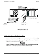
Mounting The Analog Terminal Interface
Refer to Section 2.1 at the beginning of this chapter for system mounting considerations that are
also applicable to the analog terminal interface.
Mounting Procedure
1. Unpack and carefully inspect the ATI-D for shipping damage. Notify the shipper
immediately of any damage found. Verify that the package contains all parts and accessories
needed for proper installation and operation.
2. If a backboard is required at the mounting location, attach it securely to provide a stable
mounting surface.
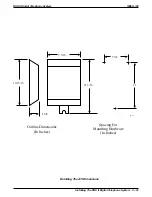
3. Use the base of the ATI-D as a template or measure for mounting hole locations per the
dimension details shown in the illustration on the next page.
4. Drill holes of a proper size to accommodate the hardware being used into the mounting
surface. If necessary, prepare these holes with inserts, anchors or other attachment devices as
dictated by the type of mounting surface.
5. Insert the two top screws into the mounting surface and tighten them to within approximately
1/8-inch of the surface.
6. Hang the ATI-D on the top screws using the mounting holes located on the rear of the
cabinet. Note that these holes are elongated with an enlargement at one end. This feature
allows the cabinet to snap down on the screws to secure the mounting when the cabinet is
hung on them.
7. Insert a third screw through the mounting tab located on the lower edge of the cabinet and
into the mounting surface; tighten it into place.
IMI66–132
DSU II Digital Telephone System
2 – 66 Installing The DSU II Digital Telephone System
Содержание DSU II
Страница 31: ......


