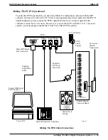
Setting The Caller ID Parameter Switches
The Caller ID device has two banks of parameter switches located on its front panel.
Set the switches of the S1 switch bank per the following rule:
•
If you are combining units (more than 8 lines are used), turn all switches in Dip Switch S1
OFF except for switch 7. Turn S1 switch 7 ON when combining units. If you are not
combining units, turn all S1 switches OFF.
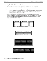
You must set the switches of the S2 switch bank in a certain manner to enable Caller ID
operation. Switches S2-1 through S2-5 set the baud rate, data bits, and parity, while switches
S2-6, S2-7, and S2-8 set the unit address for each device. Set the switches of the S2 per the
details shown in the following tables.
SWITCH S2-1
SWITCH S2-2
BAUD RATE
OFF
OFF
1200
ON
OFF
2400
OFF
ON
4800
ON
ON
9600*
* Set ON, ON (9600 baud) for DSU operation.
SWITCH S2-3
DATA BITS
OFF
7
ON
8*
*Set ON (8 data bits) for DSU operation.
SWITCH S2-4
SWITCH S2-5
PARITY
OFF
OFF
NO PARITY*
ON
OFF
ODD
OFF
ON
EVEN
ON
ON
EVEN
* Set OFF, OFF (no parity) for DSU operation.
SWITCH S2-6
SWITCH S2-7
SWITCH S2-8
DEVICE
OFF
OFF
OFF
1
ON
OFF
OFF
2
OFF
ON
OFF
3
IMI66–132
DSU II Digital Telephone System
2 – 78 Installing The DSU II Digital Telephone System
Содержание DSU II
Страница 31: ......

