2-5
Cisco SFS 3504 Multifabric Server Switch Hardware Installation Guide
OL-14325-01
Chapter 2 Preparing to Install
Site Requirements
Preventing Electrostatic Discharge Damage
ESD damage, which can occur when modules or other FRUs are improperly handled, results in
intermittent or complete failures. Modules consist of printed circuit boards that are fixed in metal
carriers. EMI shielding and connectors are integral components of the carrier. Although the metal carrier
helps to protect the circuit board from ESD, always use an ESD grounding strap when handling modules.
Air Flow
Note
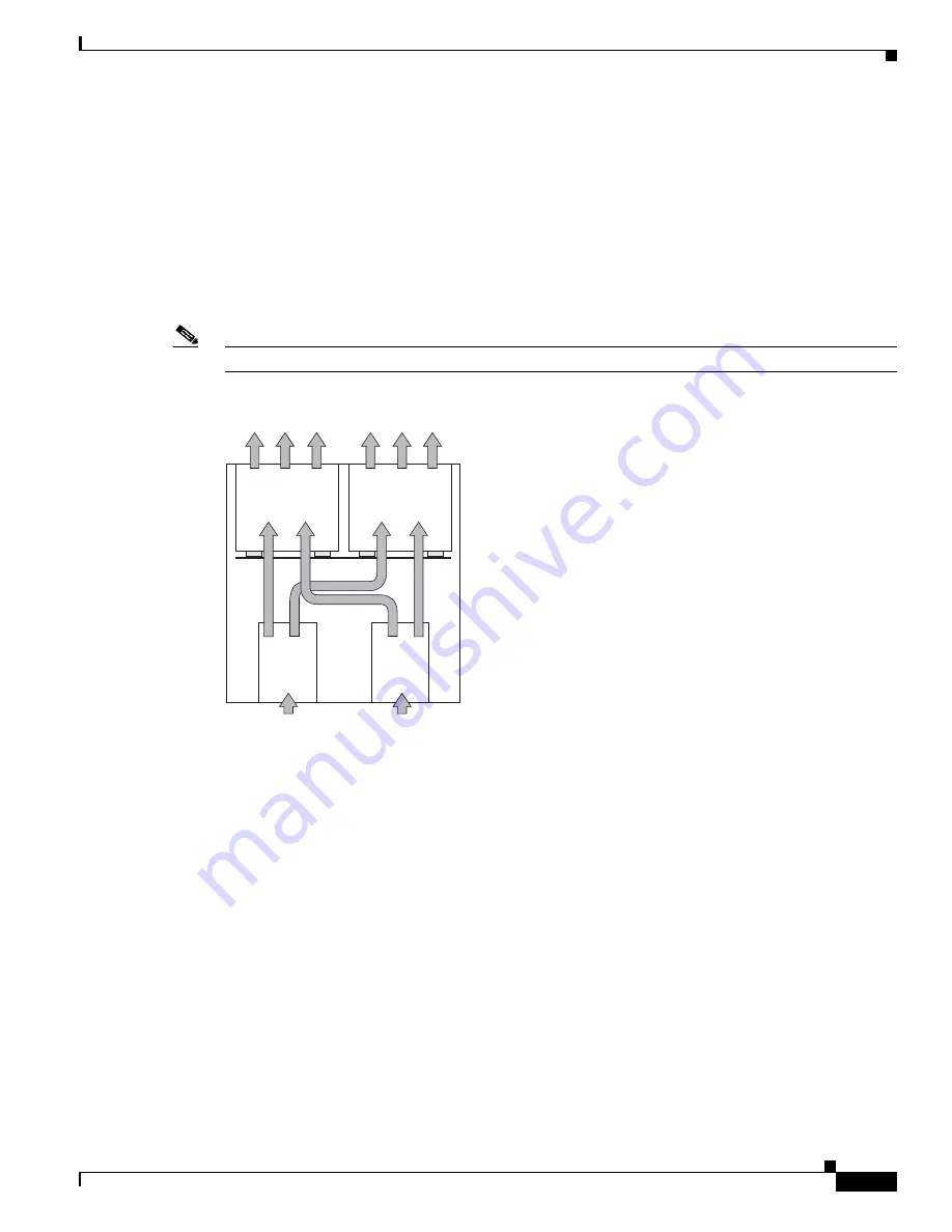
Air flows through the Cisco SFS 3504 Server Switch from rear to front. (See
Figure 2-1
.)
Figure 2-1
Air Flow Direction in the Cisco SFS 3504 Server Switch
Follow these guidelines to ensure proper airflow:
•
Maintain ambient airflow throughout the data center to ensure normal operation.
•
If installing in an enclosed cabinet, ensure that the cabinet has adequate ventilation, and allow at
least 2.5 inches (6.4 cm) of clearance between the chassis vents and the cabinet doors.
•
If placing the switch adjacent to a device that exhausts air towards the switch, the horizontal distance
between the devices should be a minimum of 6 inches (15.2 cm).
•
Ensure that cables do not obstruct the airflow through the chassis.
•
Consider heat dissipation of all equipment when determining the air-conditioning requirements, as
specified in the hardware installation guide. When evaluating airflow requirements, consider that
hot air generated by equipment at the bottom of the rack can be drawn into the intake ports of the
equipment above.
250242
Gateway
Front
Midplane
Gateway
Rear
Air flow
Air flow
Power
supply
1
Power
supply
2


