


1-4
Cisco SFS 3504 Multifabric Server Switch Hardware Installation Guide
OL-14325-01
Chapter 1 Cisco SFS 3504 Server Switch Overview
Cisco SFS 3504 Server Switch Chassis
Cisco SFS 3504 Server Switch Chassis
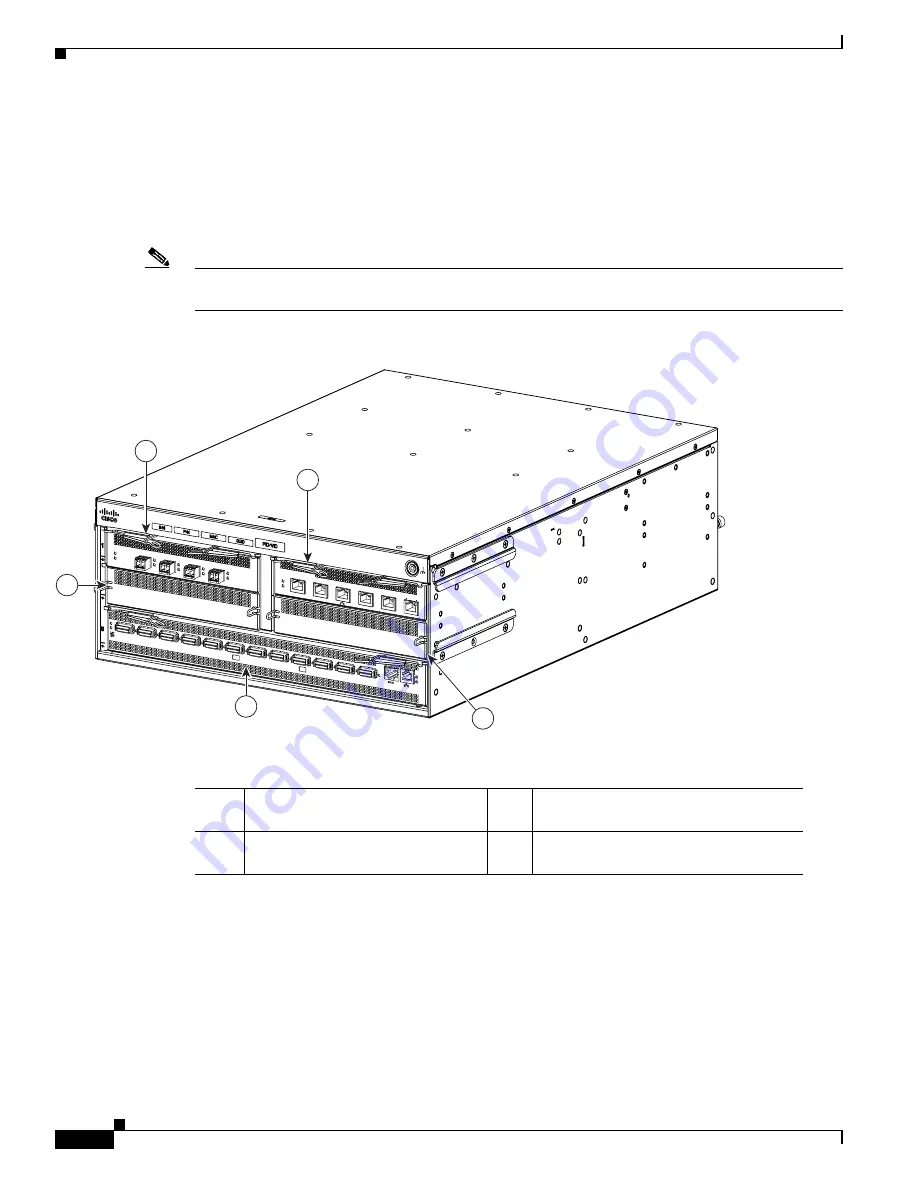
Figure 1-2
displays the data connection end of the Cisco SFS 3504 Server Switch and numbers the slots
on the chassis. FRUs with interfaces populate the data connection end of the chassis.
Figure 1-2
is an
example of a typical Cisco SFS 3504 Server Switch configured with one Fibre Channel gateway module,
one Ethernet gateway module, and two filler panels in each of slots 1-4.
Note
Slots 1-4 can be populated to contain any combination of Fibre Channel gateways, Ethernet gateways,
and filler panels. Slot 5 contains an IB switch card.
Figure 1-2
Cisco SFS 3504 Server Switch in a Typical Configuration - Data Connection End
The power-fan modules populate the chassis as shown in
Figure 1-3
. They are FRUs. For details about
installing and removing FRUs, see
Chapter 4, “Installing and Removing Field-Replaceable Units.”
250152
Cisco S
FS3504 Multifabric Switc
h
!
OK
1
2
3
4
5
6
7
8
9
10
11
12
TX/RX
Link
D
1
4
2
5
3
SFS350
0 Series FC G
ateway
!
OK
1
2
3
4
Fault
Link
SFS3500 Ser
ies Ethernet Gate
way
!
OK
1
2
3
4
5
6
TX/RX
Link
100/1000Base
T
1
Slot 1—Cisco IB 4-Port Fibre
Channel gateway module
3 - 4
Slots 3 and 4—Blanking panels for I/O
slots
2
Slot 2—Cisco IB 6-Port Ethernet
gateway module
5
Slot 5—IB switch card


