• If the device does not currently have a configured IP address
or device label, the device’s Fluidmesh Mesh ID number will
be shown.
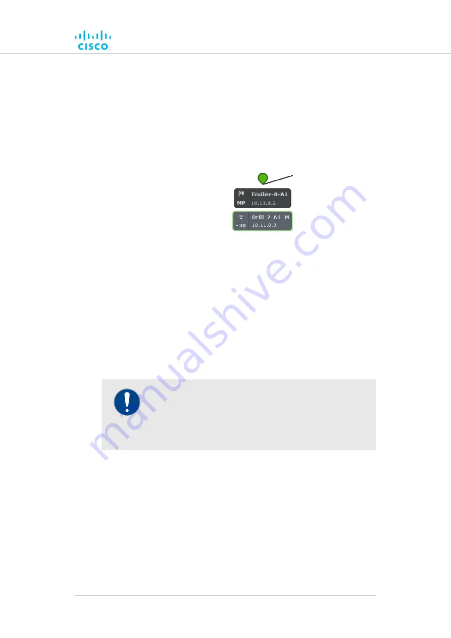
• If the network is a Fluidity network, mobile Fluidmesh radio
transceivers that are part of the network are shown as
tooltips with colored borders. The tooltip representing a
mobile Fluidmesh radio is always shown below the tooltip of
the stationary transceiver to which it is currently connected
(below).
• Mobile-radio tooltip borders are colored according to the radio’s
performance relative to its currently configured KPI thresholds:
• If LER is less than or equal to 15%, PER is 0%, and RSSI is
greater than or equal to -81 dBm, radio performance is
optimal, and the tooltip border will be green.
• If LER is between 15% and 30% or RSSI is between -86 dBm
and -81 dBm, radio performance is acceptable, and the
tooltip border will be orange.
• If LER is greater than 30%, PER is greater than 0%, or RSSI
is less than -86 dBm, radio performance is below standard,
and the tooltip border will be red.
IMPORTANT
The KPI thresholds that govern tooltip border color cannot be
changed.
If you need to adjust KPI thresholds to custom values, you
must use FM Monitor as the primary network monitoring tool.
If a mobile radio connected to a stationary radio hands off to another
stationary radio, the tooltip representing the mobile radio will move to a
position underneath the connected stationary radio. If a stationary or
mobile radio is disconnected from the network or cannot be reached, it will
not be shown in the FM-QUADRO view.
Network connectivity links between stationary radio transceivers are
shown as lines:
• A wired LAN link is shown as a solid black line (below).
Device configuration using the configurator interface
© 2021 Cisco and/or its affiliates. All rights reserved.
Page 57 of 138


