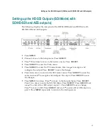


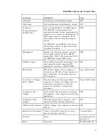


Connecting the Input/Output Signals
35
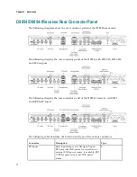
External Alarm System Connector
The D9854/D9854-I receiver and Alarm relay functionality. See
Cue Tone/Cue
Trigger Interface
(on page 36) for more information on Cue Tone and Cue Trigger
equipment connections. These outputs are user-configurable via the Setup Menu on
the front panel.
The Alarm output connector is a 15-pin sub-D female connector. The following
diagram shows the connector and the pin allocation table for the Alarm output pins.
The connector pin states depend on the selected Relay Mode. The Relay Mode is set
on the front panel via the Main: Setup: Outputs menu.
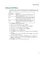
Changing the Relay Mode for Alarm Monitoring
The Alarm relay is a program relay that can be configured to provide programmed
responses for alarms, warnings, cue trigger states for ad-insertion equipment, or a
cue tone output for connection to ad-insertion equipment. As a default, the Alarm
Relay is configured for Alarm mode.
1
On the front panel menu, go to the Main: Setup: Outputs, and select
Cueing
.
2
Use the down arrow key to scroll through the menu to Relay Mode.
3
Change the state to
Alarm
and press the
Select
key to save the new setting. As a
result, the rear panel connector pin states will change to that shown in the table
below for Alarm mode.
Connector
Normally
closed pin
Common pin Normally open
pin
Relay Mode
1
15
10
CUE TONE/RELAY
11
10
15
Trigger
15
10
11
Alarm (default)
Note:
A Normally closed state implies the state when power is applied to the relay
in a normal operating state, without a trigger or alarm condition present.
Connecting the RS-232 Data Interface
The DCE DB-9 female connector is intended for low-speed data: 7 bits, even parity, 1
stop bit, up to 38.4 kb/s (default). These outputs are user-configurable via the Setup
Menu on the front panel.
The interconnect cable from the D9854/D9854-I receiver to a PC should be straight
through (for example, no handshaking), shielded and equipped with a DB-9 male
connector at one end to mate with the rear panel RS-232 Data interface, and a female
DB-9 connector to connect to the PC.
Содержание D9854
Страница 21: ...Declaration of Conformity 410 Index 411 ...
Страница 22: ......
Страница 24: ......
Страница 28: ...Chapter 1 Introduction 4 SCTE 104 pass through support on SDI output NIT Retune Recovery ...
Страница 36: ......
Страница 48: ......
Страница 66: ......
Страница 180: ......
Страница 328: ......
Страница 392: ......
Страница 394: ......
Страница 412: ......
Страница 434: ...Appendix C Compliance 410 Declarationof Conformity ...
Страница 439: ......