


Chapter 5 Web GUI Setup and Monitoring
166
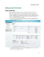
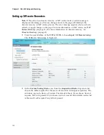
3
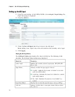
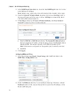
Choose
UserCfg
from the
Input Selection
drop-down list to lock to the RF input
set by the user. Choose
SW Map
to use the orbital position settings to select the
RF input. We recommend that you validate the orbital position for the SW Map
option.
4
Click the
Use RF 1
,
Use RF 2
,
Use RF 3
,
or
Use RF 4
radio button to select an RF
input to activate.
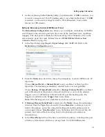
5
In the
Tuning
area, enter the current operating downlink frequency used by the
receiver for tuning the received digital signal in the
Downlink Frequency
field.
You can enter a value in the range from 0.0 to 15.0 GHz.
6
In the
Symbol Rate
field, type the symbol rate. The symbol rate must match that
of transmitted signal. You can enter a value in the range from 1.0 to 45.0 Ms/s for
DVB-S, 1.0 to 30.0 for DVB-S2 if Pilot Present is set to Yes on the front panel, or
5.0 to 30.0 for DVB-S2 if Pilot Present is set to No on the front panel.
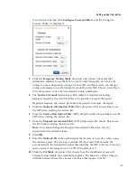
7
Choose the Forward Error Correction inner code rate from the
FEC
drop-down
list. The FEC rate must match the FEC of the transmitted signal. You can select
1/2, 2/3, 3/4, 5/6, 7/8, or Auto.
8
From the
Modulation
drop-down list, select the modulation type for the
received signal (DVB-S or DVB-S2).
9
From the
Roll Off
drop-down list, choose the
roll off factor of the incoming
signal (.20, .25, .35). Set the value to .20 or .35 when DVB-S modulation is used,
and either of the three when DVB-S2 is used. Use a small number to reject or
filter carriers close to the same frequency.
10
Choose the input signal spectrum inversion setting from the
IQ
drop-down list,
which allows the operator to track and select inverted and non-inverted digital
signals. This is normally used to automatically reject or filter out unwanted
signals.
When set to Auto, signal is tracked and inverted for correct selection, as
required. When set to Opposite, the signal is always inverted. Conversely, when
set to Normal, the signal is not inverted.
11
The
RF1 22KHz
is only applicable for dual band applications. Select whether to
transmit the 22 kHz tone Local Oscillator control signal of RF1. The selections are
On, Off, or Auto. Select Auto to use the crossover frequency to determine if the
tone is transmitted.
12
From the
RF1 Power
drop-down menu, choose the power output of RF1 to the
external Low Noise Block (LNB).
You can set the RF1 Power to Off, 13V, 18V, V-NIT or H-NIT. When RF1 Power
is set to V-NIT or H-NIT, it will use vertical and horizontal polarity until it is
automatically read from the NIT.
Note:
Power will not be applied to the LNB when set to Off.
13
In the
RF Input LNB Configuration
area, for RF1, RF2, RF3, and/or RF4, set the
lower local oscillator frequency, in GHz, of the LNB in the
LO1 (Ghz)
column. If
it is a single band oscillator, set its frequency, in GHz. You can enter a value in a
range from 0.0 to 15.0 GHz. This value must be lower than the value for LO2.
Содержание D9854
Страница 21: ...Declaration of Conformity 410 Index 411 ...
Страница 22: ......
Страница 24: ......
Страница 28: ...Chapter 1 Introduction 4 SCTE 104 pass through support on SDI output NIT Retune Recovery ...
Страница 36: ......
Страница 48: ......
Страница 66: ......
Страница 180: ......
Страница 328: ......
Страница 392: ......
Страница 394: ......
Страница 412: ......
Страница 434: ...Appendix C Compliance 410 Declarationof Conformity ...
Страница 439: ......