


Chapter 3 Installation
32
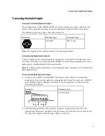
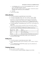
Connecting the Input/Output Signals
Connecting the RF Inputs
Connect up to four LNB RF cables to the RF connectors labeled RF1 through RF4 on
the rear of the unit.
Use 75-ohm (braid/foil or braid/braid), low insertion loss coaxial cable.
Each input accepts an LNB signal input. RF2 to RF4 require an external LNB power
source.
Connecting the ASI Input
If desired, connect to the ASI IN port to an asynchronous serial interface for uplink
monitoring.
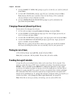
Connecting the Video Outputs
The video output connectors are of the BNC type.
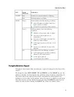
The following table shows the video connector:
Connector
Interface type
Connector type
SMPTE-292M
BNC female
Connecting the Component Video Output
Connect a video monitor to the connectors labeled Pr, Pb, and Y.
Connecting the Composite Video Output
Connect a video monitor to the CVSB 1 and CVSB 2 connectors. The two outputs are
identical. Use a 75-ohm double-braided coax cable.
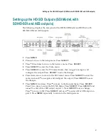
Connecting the HD-SDI Outputs
Connect HD rebroadcast equipment to the connectors labeled M1 and M2, and/or if
required, connect them to a video monitor.
There are two connectors to provide active loop-through possibility.
Содержание D9854
Страница 21: ...Declaration of Conformity 410 Index 411 ...
Страница 22: ......
Страница 24: ......
Страница 28: ...Chapter 1 Introduction 4 SCTE 104 pass through support on SDI output NIT Retune Recovery ...
Страница 36: ......
Страница 48: ......
Страница 66: ......
Страница 180: ......
Страница 328: ......
Страница 392: ......
Страница 394: ......
Страница 412: ......
Страница 434: ...Appendix C Compliance 410 Declarationof Conformity ...
Страница 439: ......